Theory / Math
Understanding Radiometry
This is my second note on studying ReSTIR: Understanding Radiometry.
Introduction
Ultimately, all you need is a four-component RGBA color as the result of the rendering process. Whatever happens inside the renderer black box is just details. But to understand how a color is produced in rendering, one must understand two topics: colorimetry and radiometry. The former deals with colors: how we perceive, define, and process color. The latter deals with lights; how light travels, scatters, and transmits energy. ReSTIR is about illumination, and is not a paper on spectral rendering, so it is okay for us to learn radiometry for now.
According to physics, light could be either an aggregation of particles called photons, or a wave. It is beneficial for us to think of lights as photons in radiometry. A photon carries an energy that is often translated into heat when it hits atoms. In the rendering world, this energy represents the intensity of the light: how bright is the light?
Physics
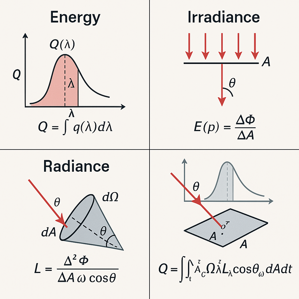
Energy
Now let’s talk some physics. We said a photon carries an energy measured in joules(J). Say that we have a closed space with total energy of Q. This energy has no context for the color. The closed space could be filled with redder lights, causing more energy near a specific wavelength. Say that we want to know how much “red” energy is in the space to compute the redness of the space. We can define an interval of wavelengths that defines “redness” and check how much energy that specific wavelength interval has. Thus:
\[Q = \int{q\left(\lambda\right)d\lambda}\]Where q stands for the energy in a given differential wavelength, and $\lambda$ stands for the wavelength.
The value of q would be almost zero in the most delta $\lambda$’s. Think of this as a population test. To tell how crowded a country is, just as population density tells us people per unit area, rather than total population, energy density tells us how much light energy exists per unit wavelength, giving us more helpful insight into the spectral distribution of light. We can define the density of the energy as:
\[\begin{align*}Q_{\lambda}&=\frac{\int_{\lambda-\frac{\Delta\lambda}{2}}^{\lambda+\frac{\Delta\lambda}{2}}{q\left(\lambda\right)d\lambda}}{\Delta\lambda}\\&=\frac{\Delta q}{\Delta \lambda}\end{align*}\]This energy considers the wavelength; thus, we call it spectral energy. It is the density of energy in a given wavelength interval.
Power
We need one more physical dimension to consider: the time. The amount of energy transferred/converted per unit time is called power, measured in watts(W). So, in theory, a 100W light bulb emits 100J of light energy per second. Of course, to be physically correct(no pun intended), the resulting omission would be less than 100J due to some heat loss, but say that it does emit 100J for simplicity. Let’s say we use a light emitting $\lambda = 500$ nm photons. According to the equation between photon energy and its wavelength:
\[Q = \frac{hc}{\lambda}\]We can calculate that the resulting photon energy is:
\[\begin{align*} Q &= \frac{hc}{\lambda}\\ &= \frac{hc}{500\textrm{nm}}\\ &= \frac{hc}{500 \times 10^{-9}\textrm{m}}\\ &\approx \frac{h\times3\times10^8\textrm{ms}^{-1}}{500 \times 10^{-9}\textrm{m}}\\ &= h \times 6\times10^{14}\textrm{s}^{-1}\\ &\approx 4 \times 10^{-19} \textrm{J} \end{align*}\]Approximately $10^{20}$ photons are produced each second. Even modern computers cannot afford to calculate this massive amount of photons, albeit short the intervals are.
In computer graphics, we call this power Radiant flux or Radiant power.
Again, we are interested in the spectral power or spectral flux, measured in W(nm)-1. The standard symbol used to represent the power is $\Phi$, and use $\Phi_{\lambda}$ to describe the spectral power.
If the light bulb distributed photons uniformly across the wavelength from 300 nm to 800 nm, then the spectral power (the density of the power across a given wavelength) is 100W/500 nm = 0.2 W(nm)-1.
\[\begin{align*} \Phi &= \frac{\Delta q}{\Delta t}\\ \Phi_{\lambda} &= \frac{\Delta q}{\Delta t\Delta \lambda}\\ \end{align*}\]Irradiance
When we perform rendering, we want to know what color each pixel has. The color of each pixel, or the points in view, is determined by the incoming lights and the material property of the point. Even if the point has the whitest material in the world, if there are no incoming lights, the surface couldn’t scatter any photons, thus the point would be rendered black. On the other hand, even if you shed the brightest light in the world, if the material property of the given point is to absorb every photon’s energy, the point would be rendered black.
Let’s focus first on the incoming lights. We should use density again when defining the number of photons traveling into a specific point per unit time. Given a finite area A, we can determine the power density over the area as E = $\Phi / A$. This could be both irradiance (E), the density of lights coming into the area A, and radiance exitance (M), the density of lights exiting the area A. Beware, radiance, exitance, and irradiance are different concepts!!
For example, say that a light bulb uniformly emits light in every spherical direction. If we put the radius of the sphere as r, then the area is $4\pi r^2$, making the radiance exitance of a point p:
\[\begin{align*} M{\left(\textbf{p}\right)} = \frac{\Phi}{4\pi r^2} \end{align*}\]Now, let’s generalize this into a differential area:
\[\begin{align*} E{\left(\textbf{p}\right)} = \frac{\Delta \Phi{\left(\textbf{p}\right)}}{\Delta A} \end{align*}\]Thus, if we sum every irradiance over an entire area, we get the power:
\[\begin{align*} \Phi = \int_{A}{E{\left(\textbf{p}\right)}dA} \end{align*}\]Because this quantity concerns an area, we must consider the direction of the lights. For example, the brightest way to shed light on a surface is to send the light directly to the area. If we tilt the light source to the surface, the lights weaken. This is because the area where the light comes from becomes larger when the light hits the surface. The same beam of light covers a larger projected area when it hits a surface at an oblique angle. Thus, the energy per unit area decreases proportionally to the cosine of the incident angle $\theta$ — which leads to the cosine factor in irradiance and the rendering equation.
Radiance
Now we can focus on the outgoing light. When discussing irradiance, we only considered time and area (and wavelength for spectral irradiance). An outgoing light adds another parameter to the equation: “direction”. In computer graphics, we parameterize direction using a concept called solid angle. A solid angle measures the field of view from the center to the outer edge of the sphere. Think of a toy globe and a marker. Draw a random point on the globe, then slice the outer edge of the point to the center of the globe. This will create a cone with an oval bottom. Just like an angle, if the sphere is a unit sphere, then the area of this oval bottom is the solid angle.
\[\begin{align*} L = \frac{\Delta^2 \Phi{\left(\textbf{p}\right)}}{\Delta A\Delta \omega\cos{\theta}} \end{align*}\]$\omega$ is the solid angle, and $\theta$ is the angle that the outgoing direction $\omega$ makes with the surface A. This value is what we need. This is often used as “intensity” or “brightness”. If we are not dealing with spectral renderers, we multiply this by the desired color.
The spectral radiance would be:
\[\begin{align*} L_{\lambda} = \frac{\Delta^2 \Phi{\left(\textbf{p}\right)}}{\Delta A\Delta \omega\cos{\theta} \Delta \lambda} \end{align*}\]Finally, we can compute the energy with:
\[\begin{align*} Q = \int_{t}\int_{A}\int_{\omega \in \Omega}\int_{\lambda}{L_{\lambda}\cos{\theta_{\omega}}}{d\lambda d\omega dA dt} \end{align*}\]where $\Omega$ is the space of directions.
Radiance is conserved along straight paths (assuming no scattering or absorption), making it a key quantity in rendering equations.
Wrap Up
So, as a graphics engineer, you ultimately need the radiance from each pixel. Think of rays emitting from the camera to each pixel on the near plane of the view frustum. Each ray will then hit a geometry in a scene. If not, we can safely consider that the ray is hitting the sky. We calculate the radiance from the hit point to the camera for each hit. The unit area is the pixel, and the unit solid angle becomes the direction to the camera.
So, how do we calculate the radiance from a point? It requires some information about the surface. First, we need the irradiance of the hit point. Based on this irradiance, using BRDF, we can compute the radiance of the photons that reach the camera. This is a topic for another time.
In principle, all we have to know is the radiance and irradiance. However, other concepts, such as radiant flux, are also important. Radiant flux is the total amount of photonic energy in the scene in a given slice of time. This means that the amount of radiant flux is “how bright the scene is.”
Further studies lead to other concepts such as BRDF, but it is also crucial for graphics engineers to look into photometry. Perception of vision is innately subjective because of its sensor, the human. Each human being senses light differently, and the same human senses light differently at different times. To capture this effect, photometry maps the radiometric concepts into their terminologies. For example, the radiant flux in photometry is called luminous flux, and its measurement is in lumens. Irradiance corresponds to luminance, and radiance to illuminance.
Below is an image ChatGPT created based on this text. As you can see, there are some strange diagrams at the end, but I think the readers can decipher this image.