Efficient Rendering Study Notes (2022.07.19)
Forward Rendering
- Do everything we need to shade a pixelLauritzen10
- For each light
- Shadow attenuation (sampling shadow maps)
- Distance attenuation
- Evaluate lighting and accumulate
- Object rendering pass does everythingKimBarrero11
- Single pass over geometry generates “final” imagePesce14
- Lights are bound to draw calls (via uniforms)Pesce14
- Accurate culling of light influence on geometry requires CSG splitsPesce14
- Multiple lights require either loops / branches in the shaders or shader permutationsPesce14
Characteristics:
- Advantages:
- Transparency via alpha blendingOlssonBilleterAssarsson13Olsson15
- MSAA and related techniques through hardware features (much less memory storage is required)OlssonBilleterAssarsson13Olsson15
- Fastest in its baseline case (single light per pixel, “simple” shaders or even baked lighting)Pesce14
- Doesn’t have a “constant” up-front investment, you pay as you go (more lights, more textures…)
- Least memory necessary (least bandwidth, at least in theory). Makes MSAA possiblePesce14Olsson15
- Single frame bufferOlsson15
- Easy to integrate with shadowmaps (can render them one-at-atime, or almost)Pesce14
- No extra pass over geometryPesce14
- Any material, except ones that require screen-space passes like Jimenez’s SS-SSSPesce14
- Single passOlsson15
- Simple if only few lightsOlsson15
- e.g., the sun
- Varying shading models is easy
- FlexibleOlsson15
- Forward or Deferred
- Issues:
- Computing which lights affect each body consumes CPU time, and in the worst cast, it becomes an O(n × m) operationKoonce07, Ineffective light cullingLauritzen10, Light culling not efficientAndersson11Pesce14
- Object space at best
- Shaders often require more than one render pass to perform lighting, with complicated shaders requiring worst-case O(n) render passes for n lightsKoonce07Lauritzen10
- Adding new lighting models or light types requires changing all effect source filesKoonce07
- Lighting / texturing variations have to be dealt with dynamic branches which are often problematic for the shader compiler (must allocate registers for the worst case …), conditional moves(wasted work and registers) or shader permutations(combinatorial explosion)Pesce14
Shaders quickly encounter the instruction count limit of Shader Model 2.0Koonce07- Memory footprint of all inputsLauritzen10
- Everything must be resident at the same time
- Shading small triangles is inefficientLauritzen10
- Shader permutations not efficientAndersson11Pesce14Olsson15
- Expensive & more difficult decaling / destruction maskingAndersson11, Decals needs to be multiplass, lit twice.Pesce14
- Complex shaders might not run optimallyPesce14Olsson15
- Texturing and lighting (and shadowing) is done in the same pass, thus shaders can require a lot of registeres and yield limited occupancy
- Accessing many textures in sequence might create more trashing than accessing them in separate passes
- Many “modern” rendering effecs require a depth/normal pre-pass anyways (i.e. SSAO, screen-space shadwos, reflections, and so on)Pesce14
- All shading is done on geometry, which means we pay all the eventual inefficiencies (e.g. partial quads, overdraw) on all shadersPesce14Olsson15
- No shadow map reuseOlsson15
- Computing which lights affect each body consumes CPU time, and in the worst cast, it becomes an O(n × m) operationKoonce07, Ineffective light cullingLauritzen10, Light culling not efficientAndersson11Pesce14
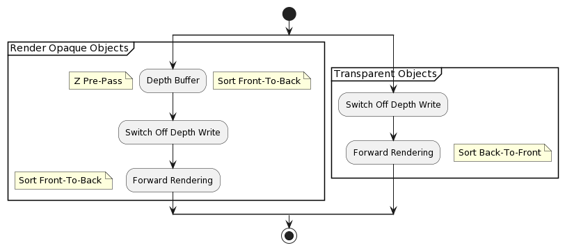
Classic forward rendering:StewartThomas13
- Depth pre-pass
- Prevents overdraw when shading
- Forward shading
- Pixel Shader
- Iterates through light list set for each object
- Evaluates material
- Diffuse texture, spec mask, bump map, etc.
- Pixel Shader
Modern Forward Shading:Olsson15
- Optional Pre-Z / Geometry Pass
- Light Assignment
- Build Light Acceleration Structure (Grid)
- Geometry Pass
- Just your normal shading pass
- For each fragment
- Look up light list in acceleration structure
- Loop over lights and accumulate shading
- Write shading to frame buffer
Z Pre-Pass rendering
Construct depth-only pass (Z pre-pass) first to fill the z buffer with depth data, and at the same time fill the z culling. Then render the scene using this occlusion data to prevent pixel overdraw.EngelShaderX709
A naïve multi-light solution that accompanies a Z pre-pass renderer design pattern would just render a limited number of lights in the pixel shader.EngelShaderX709
A more advanced approach stores light source properties such as position, light color, and other light properties in texture following a 2D grid that is laid out in the game world.EngelShaderX709
In order to render many lights:EngelSiggraph09
- Re-render geometry for each lightEngelSiggraph09
- Lots of geometry throughput
- Write pixel shader with four or eight lightsEngelSiggraph09
- Draw lights per-object
- Need to split up geometry following light distribution
- Store light properties in textures and index into this textureEngelSiggraph09
- Dependent texture look-up and lights are not fully dynamic
Space Marine:KimBarrero11
- Reject occluded objects early in G-Buffer
- Hi-Z to reject beofre ROP(Raster Operation)
- Front-to-back
- Only draw:
- maximum 75 objects
- Big enough objects in project space
- Other objects will be drawn to Z-buffer in Gbuffer pass
Unreal:Anagnostou17
- Uses reverse-Z
Lighting Pass
Single Pass Lighting
For each object:
  Render mesh, applying all lights in one shader
For each object:
  Find all lights affecting object
  Render all lighting and material in a single shader
- Good for scenes with small number of lights (e.g. outdoor sunlight)Hargreaves04
- Difficult to organize if there are many lightsHargreaves04HargreavesHarris04Valient07
- Code generation can result in thousands of combiations for a single template shaderHargreavesHarris04Valient07
- Shader for each material vs. light setup combinationValient07
- Easy to overflow shader length limitationsHargreaves04
- Hidden surfaces can cause wasted shadingHargreavesHarris04Valient07
- Hard to integrate with shadowsHargreavesHarris04
- Stencil = No Go
- Shadow Maps = Easy to overflow VRAM
- All shadow maps have to be in memoryValient07
Multipass Lighting
For each light:
  For each object affected by the light:
    framebuffer += object * light
For each light:
  For each object:
    Add lighting from single light to frame buffer
- Worst case complexity is num_objects * num_lightsHargreaves04Lee09
- Sorting by light or by object are mutually exclusiveHargreaves04
- Hard to maintain good batching
- Ideally the scene should be split exactly along light boundaries, but getting this right for dynamic lights can be a lot of CPU workHargreaves04
- Hidden surfaces can cause wasted shadingHargreavesHarris04Valient07
- High batch cound (1/object/light)HargreavesHarris04
- Even higher if shadow-casting
- Lots of repeated work each pass:HargreavesHarris04Valient07Lee09Lauritzen10
- Vertex transform & setup
- Anisotropic filtering
- Not a scalable solutionLauritzen10
- Can only be justified when targeting graphics that generally consist of low- and medium-poly-count scenes with no complex materials, a very small number of light types, and where illumination comes from a few lights spread all over the scenePlaceres06
- Shader for each material and light typeValient07
- Hard to optimize, we were often vertex boundLee09
- High vertex processing costTrebilco09
Tiled Forward Shading
- Advantages:
- Light management is decoupled from geometryOlssonAssarsson11
- Light data can be uploaded to the GPU once per sceneOlssonAssarsson11
- FSAA works as expectedOlssonAssarsson11
- Common terms in the rendering equation can be factored outOlssonAssarsson11
- Light accumulation is done in register, at full floating point precisionOlssonAssarsson11
- Same shading function as Tiled DeferredOlssonAssarsson11
- Disadvantages:
- Each fragment may be shaded more than onceOlssonAssarsson11
- Can be addressed by using a pre-z pass
- Each fragment may be shaded more than onceOlssonAssarsson11
Basic AlgorithmOlssonBilleterAssarsson13
- Subdivide screen into tiles
- (Optional): pre-Z pass
- (Optional): find min / max z-bounds for each tile
- Assign lights to each tile
- Render geometry and compute shading for each generated fragment
// 1D texture holding per-tile light lists
uniform isampleBuffer tex_tileLightLists;

// uniform buffer holding each tile's light count and
// start offset of the tile's light list (in
// tex_tileLightIndices
uniform TileLightListRanges
{
  ivec2 u_lightListRange[MAX_NUM_TILES];
}

void shading_function(inout FragmentData aFragData)
{
  // ...

  // find fragment's tile using gl_FragCoord
  ivec2 tileCoord = ivec2(gl_FragCoord.xy) / ivec2(TILE_SIZE_X, TILE_SIZE_Y);
  int tileIdx = tileCoord.x + tileCoord.y * LIGHT_GRID_SIZE_X;

  // fetch tile's light data start offset (.y) and
  // number of lights (.x)
  ivec2 lightListRange = u_lightListRange[tileIdx].xy;

  // iterate over lights affecting this tile
  for (int i = 0; i < lightListRange.x; ++i)
  {
    int lightIndex = lightListRange.y + i;

    // fetch global light ID
    int globalLightId = texelFetch(tex_tileLightLists, lightIndex).x;

    // get the light's data (position, colors, ...)
    LightData lightData;
    light_get_data(lightData, globalLightId);

    // compute shading from the light
    shade(aFragData, lightData);
  }
  // ...
}
Subdivision of Screen
- Regular N × N pixel tiles
Optional pre-Z Pass
- Required if we wish to find the Z-bounds for each tile
- In the final rendering pass, it can reduce the number of samples that need to be shaded through early-Z tests and similar hardware features
- Should only include opaque geometry
Optional Min / Max Z-Bounds
- Yields a further significant improvement
- Yields smaller per-tile bounding volumes
- Reduces the number of lights that affect a tile
Light Assignment
- CPU variant:
- Find the screen-space axis-aligned bounding boxes (AABBs) for each light source and loop over all the tiles that are contained in the 2D region of the AABB
- If min / max depth is available, perform additional test to discard lights that are outside of the tile in the Z-direction
- Find the screen-space axis-aligned bounding boxes (AABBs) for each light source and loop over all the tiles that are contained in the 2D region of the AABB
- GPU variant:
- Each tile gets its own thread group
Rendering and Shading
- For each generated sample,
- Look up which lights affect that sample by checking what lights are assigned to the sample’s tile
Transparency Support
// assign lights to 2D tiles
tilesD = build_2d_tiles();
lightLists2D = assign_lights_to_2d_tiles(tiles2D);

// draw opaque geometry in pre-Z pass and find tiles'
// extents in the Z-direction
depthBuffer = render_preZ_pass();
tileZBounds = reduce_z_bounds(tiles2D, depthBuffer);

// for transparent geometry, prune lights against maximum Z-direction
lightListsTrans = prune_lights_max(lightLists2D, tileZBounds);

// for opaque geometry additionally prune lights against
// minimum Z-direction
lightListsOpaque = prune_lights_min(lightListsTrans, tileZBounds);

// ...

// later: rendering
draw(opaque geometry, lightListsOpaque);
draw(transparent geometry, lightListsTrans);
Forward+ Rendering
- Goal:HaradaMcKeeYang13
- Materials may need to be both physically and nonphysically based
- Artists want complete freedom regarding the number of lights that can be placed in a scene at once
- Rendering data should be decoupled from the underlying rendering engine
Forward+:StewartThomas13
- Depth pre-pass
- Prevents overdraw when shading
- Provides tile depth bounds
- Separate depth prepass + depth buffer for transparentsNeubeltPettineo14
- May include vertex normal and velocityPettineo15
- Tiled light culling
- Compute shader
- Generates per-tile light list
- Transparent light list generated per-tileNeubeltPettineo14Pettineo15
- TileMinDepth = TileMin(transparentDepth)
- TileMaxDepth = TileMax(opaqueDepth)
- Culled using depth bufferPettineo15
- Async compute -> mostly freePettineo15
- Forward shading
- Pixel Shader
- Iterates through light list calculated by tiled light culling
- Evaluates material
- Diffuse texture, spec mask, bump map, etc.
- Pixel Shader
- Forward+ Light-culling stage before final shadingHaradaMcKeeYang12
- Stages:HaradaMcKeeYang12
- Depth Pre-Pass (Z prepassHaradaMcKeeYang13)
- Light CullingHaradaMcKeeYang13
- Final ShadingHaradaMcKeeYang13
- Advantages:
- Requires less memory traffic than compute-based deferred lightingHaradaMcKeeYang12
- Same memory as forward, more bandwidth, enables MSAAPesce14
- Any material (same as forward)Pesce14
- Compared to forward, no mesh splitting is necessary, much less shader permutations, less draw callsPesce14
- Compared to forward it handels dynamic lights with good cullingPesce14
- Requires less memory traffic than compute-based deferred lightingHaradaMcKeeYang12
- Disadvantages:
- Geometry submitted twiceStewartThomas13
- Small trianglesStewartThomas13
- Light occlusion culling requires a full depth pre-pass for a total of two geometrical passesPesce14
- Can be sidestepped with a clustered light grid
- All shadowmaps need to be generated upfront (more memory) or splatted in screen-space in a pre-pass
- All lighting permutations need to be addressed as dynamic branches in the shaderPesce14
- Not good if we need to support mnay kinds of light/shadow types
- Compared to forward, seems a steep price to pay to just get rid of geometry cuttingPesce14
- Even if this “solved” shader permutations, its solution is the same as doing forward with shaders that dynamic branch over light types/number of ligts and setting these parameters per draw call
Light Culling
- Similar to the light-accumulation step of deferred lightingHaradaMcKeeYang13
- Calculates a list of light indices overlapping a pixelHaradaMcKeeYang12 instead of lighting componentsHaradaMcKeeYang13
- However, per-pixel calculation has some issues:
- Memory footprint
- Efficiency of computation at light-culling stage
- However, per-pixel calculation has some issues:
- Split the screen into tiles and light indices are calculated on a per-tile basisHaradaMcKeeYang12
- Implemented using a single compute shaderStewartThomas13
- How to reduce false positives?
- Lights are too far away!
- 3D implementation uses too much memory
- 2.5 Culling!
Implementation
Gather Approach
- Thread group per tileHaradaMcKeeYang12StewartThomas13
- e.g.
[numthreads(16, 16, 1)]for 16 × 16 tile size
- e.g.
- Frustum of the tile is calculated using the range of the screen space of the tile and max/min depth values of the pixelsHaradaMcKeeYang12StewartThomas13
- Kernel first uses all the threads in a thread group to read a light to the local registerHaradaMcKeeYang12
- Overlap of the lights to the frustum of the tile is checked in parallel
- If overlaps, thread accumulates the light to TLS using local atomic operations
groupshared uint ldsLightIdx[MAX_NUM_LIGHTS_PER_TILE]StewartThomas13
- Flushes lights to the global memory using all threadsStewartThomas13
RWBuffer<uint> g_PerTileLightIndexBufferOut : register(u0);StewartThomas13
- 256 lights are culled in parallel (for 16 × 16 tile size)StewartThomas13
- Simple and effective if the number of lights is not too largeHaradaMcKeeYang12
// GET_GROUP_IDX: thread group index in X direction (SV_GroupID)
// GET_GROUP_IDY: thread group index in Y direction (SV_GroupID)
// GET_GLOBAL_IDX: global thread index in X direction (SV_DispatchThreadID)
// GET_GLOBAL_IDY: global thread index in Y direction (SV_DispatchThreadID)
// GET_LOCAL_IDX: local thread index in X direction (SV_GroupThreadID)
// GET_LOCAL_IDY: local thread index in Y direction (SV_GroupThreadID)

// No global memory write is necessary until all lights are tested
groupshared u32 ldsLightIdx[LIGHT_CAPACITY];  // Light index storage
groupshared u32 ldsLightIdxCounter; // Light index counter for the storage

void appendLightToList(int i)
{
  u32 dstIdx = 0;
  InterlockedAdd(ldsLightIdxCounter, 1, dstIdx);
  if (dstIdx < LIGHT_CAPACITY)
  {
    ldsLightIdx[dstIdx] = i;
  }
}

...

  // 1: computation of the frustum of a tile in view space
  float4 frustum[4];
  { // construct frustum
    float4 v[4];
    // projToView:
    //   takes screen-space pixel indices and depth value
    //   returns coordinates in view space
    v[0] = projToView(8 * GET_GROUP_IDX,        8 * GET_GROUP_IDY,        1.f);
    v[1] = projToView(8 * (GET_GROUP_IDX + 1),  8 * GET_GROUP_IDY,        1.f);
    v[2] = projToView(8 * (GET_GROUP_IDX + 1),  8 * (GET_GROUP_IDY + 1),  1.f);
    v[3] = projToView(8 * GET_GROUP_IDX,        8 * (GET_GROUP_IDY + 1),  1.f);
    float4 o = make_float4(0.f, 0.f, 0.f, 0.f);
    for (int i = 0; i < 4; ++i)
    {
      // createEquation:
      //   Creates a plane equation from three vertex positions
      frustum[i] = createEquation(o, v[i], v[(i + 1) & 3]);
    }
  }

  ...

  // 2: clip the frustum by using the max / min depth values of the pixels in the tile
  float depth = depthIn.Load(uint3(GET_GLOBAL_IDX, GET_GLOBAL_IDY, 0));
  float4 viewPos = projToView(GET_GLOBAL_IDX, GET_GLOBAL_IDY, depth);

  int lIdx = GET_LOCAL_IDX + GET_LOCAL_IDY * 8;
  { // calculate bound
    if (lIdx == 0)  // initialize
    {
      ldsZMax = 0;  // max z coordinates
      ldsZMin = 0xffffffff; // min z coordinates
    }
    GroupMemoryBarrierWithGroupSync();
    u32 z = asuint(viewPos.z);
    if (depth != 1.f)
    {
      AtomMax(ldsZMax, z);
      AtomMin(ldsZMin, z);
    }
    GroupMemoryBarrierWithGroupSync();
    maxZ = asfloat(ldsZMax);
    minZ = asfloat(ldsZMin);
  }

  ...

  // 3: cull lights
  // 8 x 8 thread group is used, thus 64 lights are processed in parallel
  for (int i = 0; i < nBodies; i += 64)
  {
    int il = lIdx + i;
    if (il < nBodies)
    {
      // overlaps:
      //   light-geometry overlap check using separating axis theorem
      if (overlaps(frustum, gLightGeometry[i]))
      {
        // appendLightToList
        //   Store light index to the lsit of the overlapping lights
        appendLightToList(il);
      }
    }
  }

  ...

  // 4: fill the light indices to the assigned contiguous memory of gLightIdx using all the threads in a thread group
  { // write back
    u32 startOffset = 0;

    if (lIdx == 0)
    { // reserve memory
      if (ldsLightIdxCounter != 0)
      {
        InterlockedAdd(gLightIdxCounter, ldsLightIdxCounter, startOffset);

        ptLowerBound[tileIdx] = startOffset;
        ldsLightIdxStart = startOffset;
      }
      GroupMemoryBarrierWithGroupSync();
      startOffset = ldsLightIdxStart;

      for (int i = lIdx; i < ldsLightIdxCounter; i += 64)
      {
        gLightIdx[startOffset + i] = ldsLightIdx[i];
      }
    }
  }
Scatter Approach
- Computes which tile a light overlaps and writes the light-and tile-index data to a bufferHaradaMcKeeYang12
- Thread per lightHaradaMcKeeYang12
- The data of the buffer (ordered by light index at this point) needs to be sorted by tile indexHaradaMcKeeYang12
- We want a list of light indices per tile
- Radix sort
- Run kernels to find the start and end offsets of each tile in the buffer
2.5 CullingHarada12
- Additional memory usage
- 0B global memory
- 4B local memory per work group
- Additional computation complexity
- A few bit and arithmetic instructions
- A few lines of codes for light culling
- No changes for other stages
- Additional runtime overhead
- < 10% compared to the original light culling
IDEA:
- Split frustum in z direction
- Uniform split for a frustum
- Varying split among frustums
FRUSTUM CONSTRUCTION:
- Calculate depth bound
- max/min values of depth
- Split depth direction into 32 cells
- min value and cell size
- Flag occupied cell
- 32 bit depth mask per work group
LIGHT CULLING:
- If a light overlaps to the frustum
- Calculate depth mask for the light
- Check overlap using the depth mask of the frustum
- Depth mask & Depth mask
 1: frustum[0-4] ← Compute 4 planes at the boundary of a tile
 2: z ← Fetch depth value of the pixel
 3: ldsMinZ ← atomMin(z)
 4: ldsMaxZ ← atomMax(z)
 5: frustum[5, 6] ← Compute 2 planes using ldsMinZ, ldsMaxZ
 6: depthMaskT ← atomOr(1 << getCellIndex(z))
 7: for all the lights do
 8:   iLight ← lights[i]
 9:   if overlaps(iLight, frustum) then
10:     depthMaskL ← Compute mask using light extent
11:     overlapping ← depthMaskT ∧ depthMaskL
12:     if overlapping then
13:       appendLight(i)
14:     end if
15:   end if
16: end for
17: flushLightIndices()
Shading
- Goes through the list of lights and evaluates materials using information stored for each lightHaradaMcKeeYang12
- High pixel overdraw can kill performanceHaradaMcKeeYang12
- Depth Pre-Pass is critical
#define LIGHT_LOOP_BEGIN
  int tileIndex = GetTileIndex(screenPos);
  uint startIndex;
  uint endIndex;
  GetTileOffsets(tileIndex, startIndex, endIndex);

  for (uint lightListIdx = startIdx; lightListIdx < endIdx; ++lightListIdx)
  {
    int lightIdx = LightIndexBuffer[lightListIdx];
    LightParams directLight;
    LightParams indirectLight;

    if (isIndirectLight(lightIdx))
    {
      FetchIndirectLight(lightIdx, indirectLight);
    }
    else
    {
      FetchDirectLight(lightIndex, directLight);
    }
#define LIGHT_LOOP_END
  }

...

float4 PS( PSInput i ) : SV_TARGET
{
  float3 colorOut = 0;
#LIGHT_LOOP_BEGIN
  colorOut += EvaluateMicrofacet(directLight, indirectLight);
#LIGHT_LOOP_END
  return float4(colorOut, 1.f);
}
Render PassesHaradaMcKeeYang13
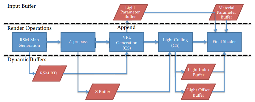
One-Bounce Indirect IlluminationHaradaMcKeeYang13
- Generate a reflective shadow map(RSM) of the scene from the point of view of the light
- Normal buffer, color buffer, world-space buffers are generated
- CS is executed to create spotlights at the location captured in the RSM
- Generated spotlights are appended to the main light list
Forward++ RenderingStewartThomas13
- Alpha Blended Geometry
- Shadow Casting Lights
- Global Illumination using VPLs
- Optimizations for depth discontinuities
Alpha Blended Geometry
- Can’t use the opaque scene’s light lists
- Frustum’s z extent was based on the opaque z-buffer
- Render blended geometry to new z-buffer
- Compute new set of tiled light lists
- minZ calculated from blended z-buffer
- maxZ calculated from opaque z-buffer
- Render blended scene using new light lists
- Geometry rendered using two-sided lighting
- Suitable for window glass & game objects
- Particle systems are better off using a custom method
- Calculating list of lights per emitter
- Lighting in vertex shader
- Two-sided lighting:
- Lighting func that accumulates lighting for front and back faces
Shadow Casting Lights
- Render shadow maps
- 2D Texture Atlas or Texture Array
- For each shadow casting lights, store shadow map index in alpha channel of light color
- Use dynamic branch in forward lighting pass to compute shadow term
// global list of lights (shadow casting + non-shadow casting)
uint shadowIndex = uint(g_PointLightColor[lightIndex].a * 255.0);
if (shadowIndex < 255)  // is it shadow casting?
{
  // Point light
  int face = DirectionToCubeMapFace(lightDirection);

  // pixel position to light space where the cube map faces
  float4 texCoord = mul(float4(position, 1), g_ShadowViewProj[shadowIndex][face]);
  texCoord.xyz /= texCoord.w;
  texCoord.xy = 0.5 * texCoord.xy + 0.5;

  // undersample per face
  texCoord.xy *= g_ShadowScaleAndBias.xx;
  texCoord.xy *= g_ShadowScaleAndBias.yy;

  // set texture coordinates in the atlas
  texCoord.xy += float2(face, shadowIndex);
  texCoord.xy *= rcp(float2(6, MAX_POINT_LIGHT_SHADOWS));

  texCoord.z -= g_ShadowZBias;

  // hardware PCF
  shadowTerm = FilterShadow(g_PointLightShadowAtlas, texCoord.xyz);
}
- Only update shadow maps if necessary
- If geometry has changed
- If lighting position has changed
- Spread cost of update over multiple frames
- Be mindful of multi GPU scenarios
- Index into projected texture in similar manner to shadow maps
- Bit pack the index along with the shadow map index
Depth Discontinuities
- Reduce false positives at depth discontinuities
- Two methods presented
- Split depth range in two at halfway point
- Keep two light lists per tile (one for each depth region)
- In the forward shading pass, each pixel determines which list to use
- 2.5D, partition depth range into 32 cells
- Determine the cell for each pixel in the tile
- Make a bit mask representing which cells are occupied in that tile
- Each light gets a similar bit mask (easy for spheres)
- Logical AND the light bit mask with the tile bit mask
- Split depth range in two at halfway point
Clustered Forward+Leadbetter14
- Avoids the need for a depth pre-pass by calculating light lists at multiple depths for each sub-rectangle and using the most appropriate cluster during surface shading.
Deferred Rendering
Goal:
Q: Why deferred rendering?
A: Combine conventional rendering techniques with the advantages of image space techniquesCalver03
- Advantages:
- Lights major cost is based on the screen area coveredCalver03, Predictable performance proportional to the lights’ screen-space areasShishkovtsov05Valient07
- All lighting is per-pixel and all surfaces are lit equallyCalver03Thibieroz04
- Lights can be occluded like other objects, this allows fast hardware Z-RejectCalver03
- Shadow mapping is fairly cheapCalver03
- Easily integrates with popular shadow techniquesHargreavesHarris04Placeres06
- Excellent batchingHargreaves04, Greatly simplifies batchingHargreavesHarris04, Cuts down on large numbers of batchesShishkovtsov05
- Render each triangle exactly onceHargreaves04, Only a single geometry pass is requiredThibieroz04Lee09Thibieroz11, Executes only texturing on geometry so it suffers less from partial quads, overdrawPesce14Olsson15
- Shade each visible pixel exactly onceHargreaves04, “Perfect” O(1) depth complexity for lightingHargreavesHarris04Thibieroz04, Perfect depth complexity for lightingShishkovtsov05Placeres06KnightRitchieParrish11Olsson15
- Easy to add new types of lighting shaderHargreaves04Koonce07
- Other kinds of postprocessing(blur, heathaze) are just special lights, and fit neatly into the existing frameworkHargreaves04, Simplifies rendering of multiple special effectsPlaceres06, G-Buffer already produces data required for post-processingThibieroz11
- Simple engine managementHargreavesHarris04Shishkovtsov05
- Lots of small lights ~ one big lightHargreavesHarris04HargreavesHarris04
- Forward can do it too!OlssonBilleterAssarsson13
- Reduces CPU usageShishkovtsov05
- Lighting costs are independent of scene complexityKoonce07Stewart15, Adding more layers of effects generally results in a linear, fixed cost per frame for additional full-screen post-processing passes regardless of the number of models on screenFilionMcNaughton08EngelShaderX709EngelSiggraph09Kaplanyan10KnightRitchieParrish11Thibieroz11
- No additional render passes on geometry for lighting, resulting in fewer draw calls and fewer state changes required to render the sceneKoonce07EngelSiggraph09Thibieroz11, Less draw calls, less shader permutations, one or few lighting shaders that can be hand-optimized wellPesce14Schulz14
- Material shaders do not perform lighting, freeing up instructions for additional geometry processingKoonce07
- Simpler shadersValient07
- More complex materials can be implementedLee09
- Not all buffers need to be updated with matching data, e.g., decal tricks
- Faster lightingKnightRitchieParrish11
- Decouples texturing from lightingPesce14Stewart15
- Potentially can be faster on complex shadersPesce14
- Allows volumetric or multipass decals (and special effects) on the G-Buffer (without computing the lighting twice)Pesce14
- Allows full-screen material passes like analytic geometric specular antialiasing (pre-filtering), which really works only done on the G-BufferPesce14
- Fails in forward on all hard edges (split normals), and screen-space subsurface scatteringPesce14
- Trivial light managementOlsson15
- Enables many lights
- Simple (light) shader managementOlsson15
- Shadow map reuseOlsson15
- Disadvantages:
- Large frame-buffer sizeCalver03, Framebuffer bandwidth can easily get out of handHargreaves04Placeres06EngelSiggraph09Kaplanyan10Thibieroz11OlssonBilleterAssarsson13Pesce14Olsson15
- Potentially high fill-rateCalver03Placeres06Kaplanyan10Lauritzen10OlssonBilleterAssarsson13StewartThomas13Pesce14Olsson15Arntzen20
- Reading lighting inputs from G-Buffer is an overheadLauritzen10
- Accumulating ligthing with additive blending is an overheadLauritzen10
- Requires high precisionOlsson15
- Multiple light equations difficultCalver03, Forces a single lighting model across the entire scene (everything has to be 100% per-pixel)Hargreaves04
High hardware specificationsCalver03- Transparency is very hardCalver03, Alpha blending is a nightmare!Hargreaves04Placeres06Valient07Kaplanyan10OlssonAssarsson11, Forward rendering required for translucent objectsThibieroz11OlssonBilleterAssarsson13Pesce14Olsson15Arntzen20
- If a tiled or clustered deferred is used, the light information can be passed to a forward+ pass for transparencies
- Can’t take advantage of hardware multisamplingHargreaves04 AA is problematicHargreavesHarris04Placeres06 MSAA difficult compared to Forward RendererEngelSiggraph09Kaplanyan10OlssonAssarsson11, Costly and complex MSAAThibieroz11StewartThomas13
- MYTH!! MSAA did not prove to be an issue!!Valient07
- Existing multi-sampling techniques are too heavy for deferred pipelineKaplanyan10
- Post-process antialiasing doesn’t remove aliasing completelyKaplanyan10
- Need to super-sample in most cases
Not good approach for older hardwareHargreaves04Not good when you have many directional lightsHargreavesHarris04Shading complexity will be O(R * L) (R = screen resolution, L = lights)- MYTH!!Shishkovtsov05
- Recalculate full lighting equation for every lightEngelSiggraph09
- Limited material representation in G-BufferEngelSiggraph09, Limited materials variationsKaplanyan10Pesce14
- MYTH?Lee09
- Only Phong BRDF (normal + glossiness)Kaplanyan10
- No aniso materialsKaplanyan10
- Can’t do lighting computations per object/vertex (i.e. GI), needs to pass everything per pixel in the G-BufferPesce14
- Alternative: store baked data in a voxel structured
- Accessing lighting related textures (gobos, cubemaps) might be less cache-coherentPesce14
- All lights (that cast shadows) must have their shadow maps built before the shading passOlssonAssarsson11
- Significant engine reworkThibieroz11
- In general it has lots of enticing benefits over forward, and it -might- be faster in complex lighting / material / decal scenarios, but the baseline simple lighting/shading case is much more expensivePesce14
- Difficult to do multiple shading modelsOlsson15
- Custom shaders
- No forward shading supportArntzen20
- No volumetric lightingArntzen20
For each object:
  Render to multiple targets

For each light:
  Apply light as a 2D postprocess
For each object:
  Render surface properties into the G-Buffer
For each light and lit pixel
  Use G-Buffer to compute lighting
  Add result to frame buffer
Traditional deferred shading:Andersson09
- Graphics pipeline rasterizes gbuffer for opaque surfaces
- Normal, albedos, roughness, etc.
- Render scene geometry into G-Buffer MRTStewartThomas13
- Store material properties (albedo, specular, normal, etc.)
- Write to depth buffer as normal
- Light sources are rendered & accumulate lighting to a texture (accumulation buffer)StewartThomas13
- Light volume or screen-space tile rendering
- Use G-Buffer RTs as inputsStewartThomas13
- Render geometries enclosing light areaStewartThomas13
- Combine shading & lighting for final output
Modern Deferred Shading:Olsson15
- Render Scene to G-Buffers
- Light Assignment
- Build Light Acceleration Structure (Grid)
- Full Screen Pass
- Quad (or CUDA, or Compute Shaders, or SPUs)
- For each pixel
- Fetch G-Buffer Data
- Look up light list in acceleration structure
- Loop over lights and accumulate shading
- Write shading
- Worst case complexity is num_objects + num_lightsHargreaves04
- Perfect batchingHargreaves04
- Many small lights are just as cheap as a few big onesHargreaves04
- On MMO, given the lack of control of the game environment and the poort scalability of lighting costs within a forward renderer, deferred-shading renderer is preferableKoonce07
- Object rendering pass saves all surface parametersKimBarrero11
- Lighting pass saves lighting resultKimBarrero11
- Combiner pass combines lighting result + surface material in screen spaceKimBarrero11
G-Buffers
G-Buffers are 2D images that store geometric details in a texture, storing positions, normals and other details at every pixel. The key ingredient to hardware acceleration of G-Buffers is having the precision to store and process data such as position on a per-pixel basis. The higher precision we have to store the G-Buffer at, the slower the hardware renders.Calver03
Thin G-Buffer
The smaller the better!Kaplanyan10
- Crysis 3:SousaWenzelRaine13
- Minimize redundant drawcalls
- AB details on G-Buffer with proper glossiness
- Tons of vegetation → Deferred translucency
- Multiplatform friendly
G-Buffer encoding requirements:Pesce15
- Fast when implemented in a shader
- As compact as possible
- Makes sense under linear interpolation (hardware “blendable”, for pixel-shader based decals)
- As stable as possible, and secondarily as precise as possible
Advantages:
- Unified solution across all platformsSousaWenzelRaine13
- Deferred Rendering for less BW/Memory than vanillaSousaWenzelRaine13
- Good for MSAA + avoiding tiled rendering on Xbox360
- Tackle glossiness for transparent geometry on G-Buffer
- Alpha blended cases, e.g. Decals, Deferred Decals, Terrain Layers
- Can composite all such cases directly into G-Buffer
- Avoid need for multipass
- Deferred sub-surface scattering
- Visual + performance win, in particular for vegetation rendering
What to Store?
Depth
Calver03Hargreaves04HargreavesHarris04Thibieroz04Placeres06FilionMcNaughton08EngelShaderX709EngelSiggraph09Lee09LobanchikovGruen09Kaplanyan10KnightRitchieParrish11Thibieroz11Moradin19Huseyin20Pesce20
Use depth data to reconstruct position data. Provided by the depth buffer.
Format Suggestion:
- 24bppKaplanyan10
D32Huseyin20- Reveresed-Z
- In GBuffer,
G_Buffer.z = length(Input.PosInViewSpace); - In VS,
out.vEyeToScreen = float3(Input.ScreenPos.x * ViewAspect, Input.ScreenPos.y, invTanHalfFOV); - In PS,
float3 PixelPos = normalize(Input.vEyeToScreen) * G_Buffer.z;Placeres06
float3 vViewPos.xy = INTERPOLANT VPOS * half2(2.0f, -2.0f) + half2(-1.0f, 1.0f)) * 0.5 * p vCameraNearSize * p vRecipRenderTargetSize;
vViewPos.zw = half2(1.0f, 1.0f);
vViewPos.xyz = vViewPos.xyz * fSampledDepth;
float3 vWorldPos = mul(p_mInvViewTransform, vViewPos).xyz;
// input SV_POSITION as pos2d
New_pos2d = ((pos2d.xy) * (2 / screenres.xy)) - float2(1, 1);
viewSpacePos.x = gbuffer_depth * tan(90 - HORZFOV/2) * New_pos2d.x;
viewSpacePos.y = gbuffer_depth * tan(90 - VERTFOV/2) * New_pos2d.y;
viewSpacePos.z = gbuffer_depth;
Stencil
Format Suggestion:
- 8bppHuseyin20
Stencil to mark objects in lighting groupsKaplanyan10
- Portals / indoors
- Custom environment reflections
- Different ambient and indirect lighting
Normal
Calver03Hargreaves04HargreavesHarris04Thibieroz04Placeres06Andersson09EngelShaderX709EngelSiggraph09Lee09LobanchikovGruen09Kaplanyan10KnightRitchieParrish11Thibieroz11Huseyin20Pesce20
Format Suggestions:
R10G10B10A2_FLOATHargreaves04Pesce20- 2-bit alpha reserved to mark hairPesce20
U10V10W10A2Thibieroz04,U8V8W8Q8Thibieroz04- 24bppKaplanyan10
- Too quantized
- Lighting is banded / of low quality
- RGBA8_UNORMHuseyin20
Considerations:
- Model space vs Tangent spaceThibieroz04
Optimizations:
- Reconstruct z from xy(z = sqrt(1 - x2 - y2))Hargreaves04HargreavesHarris04Placeres06
- If all the lighting is performed in view space, then the front-faced polygons are always gonig to have negative or positive Z componentsPlaceres06
Packing:
float2 pack_normal(float3 norm)
{
  float2 res;
  res = 0.5 * (norm.xy + float2(1, 1));
  res.x *= (norm.z < 0 ? -1.0 : 1.0);
  return res;
}
Unpacking:
float3 unpack_normal(float2 norm)
{
  float3 res;
  res.xy = (2.0 * abs(norm)) - float2(1, 1);
  res.z = (norm.x < 0 ? -1.0 : 1.0) * sqrt(abs(1 - res.x * res.x - res.y * res.y));
  return res;
}
Crytek:
- Because we are storing normalized normals, we are wasting 24bpp.Kaplanyan10
- Create a cube of 2563 values, and find the quantized value with the minimal error for a ray. Bake this into a cubemap of results.Kaplanyan10
- Extract the most meaningful and unique part of this symmetric cubemap
- Save into 2D texture
- Look it up during G-Buffer generation
- Scale the normal
- Output the adjusted normal into G-Buffer
- However, not “blendable”Pesce15
Baseline: XYZ
- Store all three components of the normalPranckevicius09
// Encoding
half4 encode(half3 n, float3 view)
{
  return half4(n.xyz * 0.5 + 0.5, 0);
}

// Decoding
half3 decode(half4 enc, float3 view)
{
  return enc.xyz * 2.0 - 1.0;
}
Octahdral Normal VectorsCigolleDonowEvangelakosMaraMcGuireMeyer14
Map the sphere to an octahedron, project down into the z = 0 plane, and the reflect the -z-hemisphere over the appropriate diagonal.
// float3 to oct

// returns ±1
float2 signNotZero(float2 v)
{
  return float2((v.x >= 0.0) ? +1.0 : -1.0, (v.y >= 0.0) ? +1.0 : -1.0);
}

// assume normalized input. output is on [-1, 1] for each component
float2 float3ToOct(float2 v)
{
  // project the sphere onto the octahedron, and then onto the xy plane
  float2 p = v.xy * (1.0 / (abs(v.x) + abs(v.y) + abs(v.z)));

  // reflect the folds of the lower hemisphere over the diagonals
  return (v.z <= 0.0) ? ((1.0 - abs(p.yx)) * signNotZero(p)) : p;
}
// oct to float3
float3 octToFloat3(float2 e)
{
  float3 v = float3(e.xy, 1.0 - abs(e.x) - abs(e.y));
  if (v.z < 0)
  {
    v.xy = (1.0 - abs(v.yx)) * signNotZero(v.xy);
  }

  return normalize(v);
}
Diffuse Albedo
Calver03Hargreaves04HargreavesHarris04Thibieroz04Andersson09EngelShaderX709EngelSiggraph09Lee09LobanchikovGruen09KnightRitchieParrish11Thibieroz11Moradin19Huseyin20Pesce20
Format Suggestions:
R8G8B8A8Hargreaves04Thibieroz04RGBA8_SRGBHuseyin20R10G10B10A2Pesce20
Etc.
- Specular / Exponent MapCalver03HargreavesHarris04
- EmissiveCalver03HargreavesHarris04Pesce20
R8Pesce20
- Light MapHargreavesHarris04Lee09
- Material IDCalver03HargreavesHarris04LobanchikovGruen09
- RoughnessAndersson09Moradin19Pesce20
- R8Pesce20
- AOLobanchikovGruen09Moradin19
- GlossinessLee09LobanchikovGruen09Kaplanyan10
- 8bppKaplanyan10
- Non deferrableKaplanyan10
- Required at lighting accumulation pass
- Specular is non-accumulative otherwise
- Specular PowerEngelShaderX709EngelSiggraph09Lee09
- Motion VectorEngelShaderX709EngelSiggraph09
- Velocity MaskMoradin19
- ShadowEngelShaderX709EngelSiggraph09
- Specular TermsThibieroz11
- Sky MaskMoradin19
- Vertex NormalMoradin19
- MetalnessMoradin19Huseyin20Pesce20
- Reflectance (f0)Huseyin20
R8 UNORMHuseyin20
- SmoothnessHuseyin20
R8 UNORM
- TranslucencyPesce20
R8
Examples
Example 1: Beyond3DCalver03
| MRTs | R | G | B | A |
| RT 0 | Pos.X | Pos.Y | Pos.Z | ID |
| RT 1 | Norm.X | Norm.Y | Norm.Z | Material ID |
| RT 2 | Diffuse Albedo.R | Diffuse Albedo.G | Diffuse Albedo.B | Diffuse Term |
| RT 3 | Specular Emissive.R | Specular Emissive.G | Specular Emissive.B | Specular Term |
| Material Lookup texture |
|---|
| Kspecblend |
| KAmb |
| KEmm |
| … |
Example 2: Climax Studios GDC 2004 Hargreaves04
| MRTs | R | G | B | A |
| DS | Depth R32F | |||
| RT 0 | Norm.X R10F | Norm.Y G10F | Norm.Z B10F | Scattering A2F |
| RT 1 | Diffuse Albedo.R R8 | Diffuse Albedo.G G8 | Diffuse Albedo.B B8 | Emissive Term A8 |
| RT 2 (could be palettized) | Material Parameters R8 | Material Parameters G8 | Material Parameters B8 | Material Parameters A8 |
Example 3: ShaderX2Thibieroz04
| MRTs | R8 | G8 | B8 | A8 |
| RT 0 | Pos.X R16F | Pos.Y G16F | ||
| RT 1 | Pos.Z R16F | |||
| RT 2 | Diffuse Albedo.R R8 | Diffuse Albedo.G G8 | Diffuse Albedo.B B8 | Normal.Z A8 |
| RT 3 | Normal.X A8 | Normal.Y L8 | ||
Example 4: Killzone 2Valient07
| MRTs | R8 | G8 | B8 | A8 |
| DS | Depth 24bpp | Stencil | ||
| RT 0 | Lighting Accumulation.R | Lighting Accumulation.G | Lighting Accumulation.B | Intensity |
| RT 1 | Normal.X FP16 | Normal.Y FP16 | ||
| RT 2 | Motion Vectors XY | Spec-Power | Spec-Intensity | |
| RT 3 | Diffuse Albedo.R R8 | Diffuse Albedo.G G8 | Diffuse Albedo.B B8 | Sun-Occlusion A8 |
- Position computed from depth buffer and pixel coordinates
- Lighting accumulation - output buffer
- Intensity - luminance of Lighting accumulation
- Scaled to range [0…2]
- Normal.z = sqrt(1.0f - Normal.x2 - Normal.y2)
- Motion vectors - screen space
- Specular power - stored as log2(original)/10.5
- High range and still high precision for low shininess
- Sun Occlusion - pre-rendered static sun shadows
- Mixed with real-time sun shadow for higher quality
Analysis:
- Pros:
- Highly packed data structure
- Many extra attributes
- Allows MSAA with hardware support
- Cons:
- Limited output precision and dynamic range
- Lighting accumulation in gamma space
- Can use different color space (LogLuv)
- Attribute packing and unpacking overhead
- Limited output precision and dynamic range
Example 5: StarCraft IIFilionMcNaughton08
| MRTs | R | G | B | A |
| RT 0 | Unlit & Emissive R16G16B16F | Unused | ||
| RT 1 | Normal R16G16B16F | Depth | ||
| RT 2 | Diffuse Albedo.R | Diffuse Albedo.G | Diffuse Albedo.B | AO |
| RT 3 | Specular Albedo.R | Specular Albedo.G | Specular Albedo.B | Unused |
- Depth values for lighting, fog volumes, dynamic AO, smart displacement, DoF, projections, edge detection, thickness measurement
- Normals for dynamic AO
- Diffuse and specular for lighting
Example 6: S.T.A.L.E.R: Clear SkiesLobanchikovGruen09
S.T.A.L.K.E.R. originally used a 3-RT G-Buffer:
- 3D Pos + material ID (RGBA16F RT0)
- Normal + AO (RGBA16F RT1)
- Color + Gloss (RGBA8 RT2)
S.T.A.L.E.R: Clear Skies:
- Normal + Depth + Material ID + AO (RGBA16F RT0)
- Pack AO and material ID into the usable bits of the last 16 bit fp channel of RT0
- Pack data into a 32bit
uintas a bit pattern that is a valid 16bit fp number - Cast the
uintto float usingasfloat() - Cast back for unpacking using
asuint() - Extract bits
- Pack data into a 32bit
- Pack AO and material ID into the usable bits of the last 16 bit fp channel of RT0
- Color + Gloss (RGBA8 RT1)
- Trade packing math vs. Less G-Buffer texture ops
Example 7: Split/SecondKnightRitchieParrish11
| MRTs | R | G | B | A |
| RT 0 | Diffuse Albedo.R | Diffuse Albedo.G | Diffuse Albedo.B | Specular amount |
| RT 1 | Normal.X | Normal.Y | Normal.Z | Motion ID + MSAA edge |
| RT 3 | Prelit.R | Prelit.G | Prelit.B | Specular power |
Example 8: Crysis 3SousaWenzelRaine13
| MRTs | R | G | B | A |
| DS | Depth D24 | AmbID, Decals S8 | ||
| RT 0 | Normal.X R8 | Normal.Y G8 | Gloss, Z Sign B8 | Translucency A8 |
| RT 1 | Diffuse Albedo.Y R8 | Diffuse Albedo.Cb, .Cr G8 | Specular Y B8 | Per-Project A8 |
- WS Normal packed into 2 components
- Stereographic projection worked ok in practice (also cheap)
- (X, Y) = (x / (1 - z), y / (1 - z))
- (x, y, z) = (2X / (1 + X2 + Y2), 2Y / (1 + X2 + Y2), (-1 + X2 + Y2) / (1 + X2 + Y2))
- Glossiness + Normal Z Sign packed together
- GlossZsign = (Gloss * Zsign) * 0.5 + 0.5
- Albedo in Y’CbCr color space
- Y’ = 0.299 × R + 0.587 × G + 0.114 × B
- CB = 0.5 + (-0.168 × R - 0.331 × G + 0.5 × B)
- CR = 0.5 + (0.5 × R - 0.418 × G - 0.081 × B)
- R = Y’ + 1.402 × (CR - 0.5)
- G = Y’ - 0.344 × (CB - 0.5) - 0.714 × (CR - 0.5)
- B = Y’ - 1.772 × (CB - 0.5)
Example 9: DestinyTatarchukTchouVenzon13
| MRTs | R | G | B | A |
| RT 0 | Diffuse Albedo.R R8 | Diffuse Albedo.G G8 | Diffuse Albedo.B B8 | AO A8 |
| RT 1 | Normal.X * (Biased Specular Smoothness) R8 | Normal.Y * (Biased Specular Smoothness) G8 | Normal.Z * (Biased Specular Smoothness) B8 | Material ID A8 |
| DS | Depth D24 | Stencil S8 | ||
Example 10: inFAMOUS: Second SonBentley14
| MRTs | R | G | B | A |
| RT 0 | Diffuse Albedo.R R8 | Diffuse Albedo.G G8 | Diffuse Albedo.B B8 | Shadow Refr A8 |
| RT 1 | Normal.α R16 | Normal.β G16 | Vertex Normal.α B16 | Vertex Normal.β A16 |
| RT 2 | Sun Shadow R8 | AO G8 | Spec Occl B8 | Gloss A8 |
| RT 3 | Wetness Params RGBA8 | RT 4 | Ambient Diffuse.R R16F | Ambient Diffuse.G G16F | Ambient Diffuse.B B16F | Amb Atten A16F | </tr>
| RT 5 | Emissive.R R16F | Emissive.G G16F | Emissive.B B16F | Alpha A16F |
| D32f | Depth D24 | |||
| S8 | Stencil S8 | |||
Example 11: RyzeSchulz14
| MRTs | R | G | B | A |
| RT 0 | Normal.X R8 | Normal.Y G8 | Normal.Z B8 | Translucency Luminance / Prebaked AO Term A8 |
| RT 1 | Diffuse Albedo.R R8 | Diffuse Albedo.G G8 | Diffuse Albedo.B B8 | Subsurface Scatering Profile A8 |
| RT 2 | Roughness R8 | <td colspan="3"style="background-color:rgba(127, 255, 255, 0.5); color:black">Specular YCbCr / Transmittance CbCr GBA8</td>
- Normals encoded using BFN approach to avoid 8 bit precision issues
- Specular color stored as YCbCr to better support blending to GBuffer (e.g. decals)
- Allow blending of non-metal decals despite not being able to write alpha during blend ops
- Can still break when blending colored specular (rare case that was avoided on art side)
- Specular chrominance aliased with transmittance luminance
- Exploiting mutual exclusivity: colored specular just for metal, translucency just for dielectrics
- Support for prebaked AO value but was just used rarely in the end
Example 12: Uncharted 4ElGarawany16
- 16 bits-per-pixel unsigned buffers
- Constantly moving bits around between features during production
- Lots of visual tests to determine exactly how many bits were needed for the various features
- Heavy use of GCN parameter packing intrinsics
| Channels | G-Buffer 0 | Channels | G-Buffer 1 |
|---|---|---|---|
| R | r g | R | ambientTranslucency sunShadowHigh specOcclusion |
| G | b spec | G | heightmapShadowing sunShadowLow metallic |
| B | normalx normaly | B | dominantDirectionX dominantDirectionY |
| A | iblUseParent normalExtra roughness | A | ao extraMaterialMask sheen thinWallTranslucency |
- A third optional G-Buffer is used by more complicated materials
- Interpreted differently based on the type of the material
- Fabric, hair, skin, silk, etc.
Example 13: Jurassic World: EvolutionTheCodeCorsairJWE21
- Tiled Forward Lighting
- 8 × 8 pixel tiles extruded towards the far plane to create subfrustums
- CS is dispatched per tile
- Depth Prepass
- Thin GBuffer
| MRTs | R | G | B | A |
| RT 0 | Normal.X R | Normal.Y G | Normal.Z B | Roughness A |
| RT 1 | Motion Vectors | |||
Example 14: Mafia: Definitive EditionTheCodeCorsairMDE21
| MRTs | R | G | B | A |
| RT 0 | Normal.X R16F | Normal.Y G16F | Normal.Z B16F | Roughness A16F |
| RT 1 | Diffuse Albedo.R R8 | Diffuse Albedo.G G8 | Diffuse Albedo.B B8 | Metalness A8 |
| RT 2 | Motion Vectors RGB16U | Encoded Vertex Normal A16U | ||
| RT 3 | Specular Intensity R8 | 0.5 G8 | Curvature or Thickness (for SSS) B8 | SSS Profile A8 |
| RT 4 | Emissive.R R11F | Emissive.G G11F | Emissive.B B10F | |
Example 15: Digital Combat SimulatorPoulet21
- Five
R8G8_UNORMlayers with MSAA activated- Normal using a basic encoding scheme
- Store X and Y components and reconstructing the Z
- Albedo is stored across three channels encoded using YUV
- First channel of the second layer contains the Y
- First and second channel stores the U and V
- Roughness in the first channel, metalness in the second channel
- Precomputed AO provided by texture in the first channel
- Normal using a basic encoding scheme
- Normal encoding example from SSAO:
ld_ms(texture2dmsarray)(float,float,float,float) r1.zw, r5.xyww, GBufferMap.zwxy, l(0)
ld_ms(texture2dmsarray)(float,float,float,float) r0.w, r5.xyzw, GBufferMap.yzwx, l(0)
mad r1.zw, r1.zzzw, l(0.0000, 0.0000, 2.0000, 2.0000), l(0.0000, 0.0000, -1.0000, -1.0000)
add r5.x, r1.w, r1.z
add r5.z, -r1.w, r1.z
mul r5.xz, r5.xxzx, l(0.5000, 0.0000, 0.5000, 0.0000)
add r1.z, abs(r5.z), abs(r5.x)
add r5.y, r1.z, l(-1.0000)
dp3 r1.z, r5.xyzx, r5.xyzx
rsq r1.z, r1.z
mul r5.xyz, r1.zzzz, r5.xyzx
ge r0.w, l(0.5000), r0.w
movc r5.w, r0.w, r5.y, -r5.y
Example 16: UnityLagardeGolubev18
| MRTs | R | G | B | A |
| RT 0 (sRGB) | BaseColor.R R8 | BaseColor.G G8 | BaseColor.B B8 | Specular Occlusion A8 |
| RT 1 | Normal.xy (Octahedral 12/12) RGB8 | Perceptual Smoothness A8 | ||
| RT 2 | Material Data RGB8 | FeaturesMask(3) / Material Data A8 | ||
| RT 3 | Static diffuse lighting R11G11B10F | |||
| RT 4 (Optional) | Extra specular occlusion data RG8 | Ambient Occlusion B8 | Light Layering Mask | |
| RT 5 (Optional) | 4 Shadow Masks RGBA8 | |||
Overview
- Don’t bother with any lighting while drawing scene geometryHargreaves04
- Render to a “fat” framebuffer format, using MRT to store dataHargreaves04
- Drawback of fat-format encoding is the reading speedShishkovtsov05
- Apply lighting as a 2D postprocess, using these buffers as inputHargreaves04
Example Passes
Example 1: UnityLagardeGolubev18
Opaque Material Render Pass
- Depth Prepass
- GBuffer
- Tag stencil for regular lighting or split lighting
- Render Shadow
- Async Light list generation + Light/Material classification
- Async SSAO (Use Normal buffer)
- Async SSR (Use Normal buffer)
- Deferred directional cascade shadow
- (Use Normal buffer for normal shadow bias)
- Tile deferred lighting
- Indirect dispatch for each shader variants
- Read stencil
- No lighting: skip forward material and sky
- Regular lighting: output lighting
- Split lighting: separate diffuse and specular
- Read stencil
- Indirect dispatch for each shader variants
- Forward Opaque
- (Optional) Output BaseColor + Diffusion Profile
- (Optional) Output + Tag stencil for split lighting
- SS Subsurface Scattering
- Test stencil for split lighting
- Combine lighting
Geometry Phase
Each geometry shader is responsible for filling the G-Buffers with correct parameters.Calver03
The major advantage over the conventional real-time approach to Renderman style procedural textures is that the entire shader is devoted to generating output parameters and that it is run only once regardless of the number or types of lights affecting this surface (generating depth maps also requires the geometry shaders to be run but usually with much simpler functions).Calver03
Another advantage is that after this phase how the G-Buffer was filled is irrelevant, this allows for impostors and particles to be mixed in with normal surfaces and be treated in the same manner (lighting, fog, etc.).Calver03
Some portions of the light equation that stay constant can be computed here and stored in the G-Buffer if necessary, this can be used if you light model uses Fresnel (which are usually only based on surface normal and view directional).Calver03
Killzone 2Valient07
Fill the G-Buffer with all geometry (static, skinned, etc.)
  Write depth, motion, specular, etc. properties
Initialize light accumulation buffer with pre-baked light
  Ambient, Incandescence, Constant specular
  Lightmaps on static geometry
    YUV color space, S3TC5 with Y in Alpha
    Sun occlusion in B channel
    Dynamic range [0...2]
  Image based lighting on dynamic geometry
Optimizations
Export Cost
- Render objects in front-to-back orderThibieroz11
- Use fewer render targets in your MRT configThibieroz11
- Less fetches during shading passes
- Less memory usage
- Avoid slow formatsThibieroz11
- Data PackingThibieroz11
- Trade render target storage for a few extra ALU instructions
Light Accumulation PassValient07
- Light is rendered as convex geometry
- Point light - sphere
- Spot light - cone
- Sun - full-screen quad
For each light:
  Find and mark visible lit pixels
  If light contributes to screen
    Render shadow map
    Shade lit pixels and add to framebuffer
Lighting Phase
The real power of deferred lighting is that lights are first class citizens, this complete separation of lighting and geometry allows lights to be treated in a totally different way from standard rendering. This makes the artist’s job easier as there is less restrictions on how lights affect surfaces, this allows for easy customizable lighting rigs.Calver03
Light shaders have access to the parameters stored in the G-Buffer at each pixel they light.Calver03
Add lighting contributions into accumulation bufferThibieroz11
- Use G-Buffer RTs as inputs
- Render geometries enclosing light area
Render convex bounding geometry
Read G-Buffer
Compute radiance
Blend into frame buffer
- Keep diffuse and specular separate
For each light:
  diffuse += diffuse(GBuffer.N, L)
  specular += GBuffer.spec * specular(GBuffer.N, GBuffer.P, L)
- Final full-screen pass modulates diffuse color:
framebuffer = diffuse * GBuffer.diffuse + specular
Per-Sample Pixel Shader Execution:Thibieroz09
struct PS_INPUT_EDGE_SAMPLE
{
  float4 Pos : SV_POSITION;
  uint uSample : SV_SAMPLEINDEX;
};

// Multisampled G-Buffer textures declaration
Texture2DMS <float4, NUM_SAMPLES> txMRT0;
Texture2DMS <float4, NUM_SAMPLES> txMRT1;
Texture2DMS <float4, NUM_SAMPLES> txMRT2;
// Pixel shader for shading pass of edge samples in DX10.1
// This shader is run at sample frequency
// Used with the following depth-stencil state values so that only
// samples belonging to edge pixels are rendered, as detected in
// the previous stencil pass.
// StencilEnable = TRUE
// StencilReadMask = 0x80
// Front/BackFaceStencilFail = Keep
// Front/BackfaceStencilDepthFail = Keep
// Front/BackfaceStencilPass = Keep;
// Front/BackfaceStencilFunc = Equal;
// The stencil reference value is set to 0x80

float4 PSLightPass_EdgeSampleOnly( PS_INPUT_EDGE_SAMPLE input ) : SV_TARGET
{
  // Convert screen coordinates to integer
  int3 nScreenCoordinates = int3(input.Pos.xy, 0);

  // Sample G-Buffer textures for current sample
  float4 MRT0 = txMRT0.Load( nScreenCoordinates, input.uSample);
  float4 MRT1 = txMRT1.Load( nScreenCoordinates, input.uSample);
  float4 MRT2 = txMRT2.Load( nScreenCoordinates, input.uSample);

  // Apply light equation to this sample
  float4 vColor = LightEquation(MRT0, MRT1, MRT2);

  // Return calculated sample color
  return vColor;
}
Conventional Deferred ShadingLauritzen10:
- For each light
- Use rasterizer to scatter light volume and cull
- Read lighting inputs from G-Buffer
- Compute lighting
- Accumulate lighting with additive blending
- Reorders computation to extract coherence
Modern ImplementationLauritzen10:
- Cull with screen-aligned quads
- Cover light extents with axis-aligned bounding box
- Full light meshes(spheres, cones) are generally overkill
- Can use oriented bounding box for narrow spot lights
- Use conservative single-direction depth test
- Two-pass stencil is more expensive than it is worth
- Depth bounds test on some hardware, but not batch-friendly
- Cover light extents with axis-aligned bounding box
for each G-Buffer sample
{
  sampleAttr = load attributes from G-Buffer

  for each light
  {
    color += shade(sampleAttr, light)
  }

  output pixel color;
}
uniform vec3 lightPosition;
uniform vec3 lightColor;
uniform float lightRange;

void main()
{
  vec3 color = texelFetch(colorTex, gl_FragCoord.xy);
  vec3 specular = texelFetch(specularTEx, gl_FragCoord.xy);
  vec3 normal = texelFetch(normalTex, gl_FragCoord.xy);
  vec3 position = fetchPosition(gl_FragCoord.xy);

  vec3 shading = doLight(position, normal, color,
                         specular, lightPosition,
                         lightColor, lightRange);

  resultColor = vec4(shading, 1.0);
}
Red Dead Redemption 2:Huseyin20
- Global light pass
- Fullscreen quad
- Local light pass
- Low-poly sphere shape for point light volumes
- Octahderon like shape for spotlight volumes
- Rendered back-to-front with additive blending
Plus(+) Methods: Algorithm Steps:Drobot17
- List of rendering entities
- Spatial acceleration structure with culled entity lists
- Execution algorithm per sampling point
- Traverse acceleration structure
- Iterate over existing entities
- Aka Tiled / Clustered Forward+ / Deferred+
Lighting Optimizations:LagardeGolubev18
- Focus on removing false positives
- Ex: narrow shadow casting spot lights
- False positives are more expensive in lighting pass
- Light culling execute async during shadow rendering
- List building work is absorbed by leveraging asynchronous compute
- Deferred lighting pass is not running async
- Final lighting shader has higher loop complexity and greater register pressure
- Move cost where it can be hidden
- High register pressure in lighting pass
- Light culling execute async during shadow rendering
- Hierarchical approach:
- Find screen-space AABB for each visible light
- Big tile 64 × 64 prepass
- Coarse intersection test
- Build Tile or Cluster Light list
- Narrow intersection test
- Tile:
- Based on Fine Prune Tile Lighting (FPTL)
- Build FTPL light list for tile 16 × 16
- Fine pruning: test if any depth pixel is in volume
- Aggressive removal of false positives
- One light list per tile. Allows attribute to be read into scalar registers
- Cluster:
- 32 × 32 with 64 clusters
- Use geometric series for cluster position and size
- Half of cluster (32) consumes between near and max per tile depth
- Good resolution in visible range
- Permit queries behind max per tile depth
- Particles, volume, FX
Bandwidth ProblemOlsson15
- New type of overdraw
- Light overdraw
- N lights cover a certain pixel
- N reads from the same G-Buffer location
for each light
  for each covered pixel
    read G-Buffer // repeated reads
    compute shading
    read + write frame buffer // repeated reads and writes
- Re-write loop!
for each pixel
  read G-Buffer
  for each affecting light
    compute shading
  write frame buffer
- Modern shading solution:
for each pixel
  read G-Buffer
  for each possibly affecting light
    if affecting
      compute shading
  write frame buffer
- Share between groups of similar pixels
- Lots of coherency between samples
- Coherent access
- Little storage
- Conservatice lists
Pre-Tiled Shading
Advantages:
- Precise per-pixel light cullingZhdan16
- A lot of work is done outside of the shader Weaknesses:
- Massive overdraw & ROP cost when having lots of big light sourcesAndersson11Zhdan16
- Expensive to have multiple per-pixel materials in light shadersAndersson11
- MSAA lighting can be slow (non-coherent, extra bandwidth)Andersson11
- Lighting is likely to become bandwidth limitedZhdan16
Full screen lights
For lights that are truly global and have no position and size (ambient and directional are the traditional types), we create a full screen quad that executes the pixel shader at every pixel.Calver03Hargreaves04
Global directional lights has little benefit in using deferred rendering methods on them, and it would actually be slower to resample the deferred buffers again for the entire screen.FilionMcNaughton08
Shaped lights
Shaped lights can be implemented via a full screen quad in exactly the same way of directional lights just with a different algorithm computing the lights direction and attenuation, but the attenuation allows us to pre-calculate where the light no longer makes any contribution.Calver03
OptimizationCalver03
The attenuation model I use is a simple texture lookup based on distance. The distance is divided by the maximum distance that the light can possible effect and then this is used to lookup a 1D texture. The last texel should be 0, (no constant term) if the following optimisations are to be used.
OptimizationPlaceres06
Shade only the pixels influenced by the bounding object involves rendering a full screen quad, but enabling clipping and rejection features to discard many noninfluenced pixels. This requires dynamic branching.
Light Volumes
We create a mesh that encloses the light affecting volume with any pixels found to be in the interior of the volume executing the light shader.Calver03Hargreaves04
- Each pixel most be hit once and once only. If the light volume causes the light shader to be executed more than once it will be equivalent to having n lights affecting this pixel.Calver03
- The near and far clip planes must not effect the projected shape. We need the projected geometry not to be clipped at the near and far plane as this will cause holes in our lights.Calver03
- Spot LightHargreavesHarris04
- Cone
- Point LightHargreavesHarris04
- Sphere
- Direction LightHargreavesHarris04
- Quad or Box
For convex volumes the first problem is completely removed by just using back or front face culling.Calver03Hargreaves04
We can’t remove the near plane, but we can effectively remove the far plane by placing it at infinity.Calver03
Convex volumes cover the vast majority of lights shaders (e.g. spheres for point lights, cones for spotlights, etc.) and we can adapt them to use the fast z-reject hardware that is usually available.Calver03
Dealing with the light volume rendering:Hargreaves04
- Camera is outside the light bounding mesh
- Simple back face culling (each pixel most be hit once and once only)
- Camera is inside the light bounding mesh
- Draw backfaces
- Light volume intersects the far clip plane
- Draw frontfaces
- Light volume intersects both near and far clip planes
- Light is too big
Optimizations
S.T.A.L.K.E.R case:Shishkovtsov05
- Hierarchical occlusion culling system
- Coarsest test: Sector-portal culling followed by CPU-based occlusion culling
- DX9’s occlusion query to eliminate the completely occluded lights
- Stencil mask to tag affected pixels for each light
- Sun optimization
Pass 0: Render full-screen quad only where 0x03==stencil count
        (where attributes are stored)
  If ((N dot L) * ambient_occlusion_term > 0)
    discard fragment
  Else
    color = 0, stencil = 0x01
Pass 1: Render full-screen quad only where 0x03==stencil count
  Perform light accumulation / shading
- Social Stage:Placeres06
- Filter the lights and effects on the scene to produce a smaller list of sources to be processed
- Execute visiblity and occlusion algorithms to discard lights whose influence is not appreciable
- Project visible sources bounding objects into screen space
- Combine similar sources that are too close in screen space or influence almost the same screen area
- Discard sources with a tiny contribution because of their projected bounding object being too small or too far
- Check that more than a predefined number of sources do not affect each screen region. Choose the biggest, strongest, and closer sources.
- Filter the lights and effects on the scene to produce a smaller list of sources to be processed
- Individual Stage:Placeres06
- Global Sources
- Most fill-rate expensive
- Enable the appropriate shaders
- Render a quad covering the screen
- Most fill-rate expensive
- Local Sources
- Select the appropriate level of detail.
- Enable and configure the source shaders
- Compute the minimum and maximum screen cord values of the projected bounding object
- Enable the scissor test
- Enable the clipping planes
- Render a screen quad or the bounding object
- Global Sources
- Only shade the area where the light volume intersects scene geometryHargreaves04 Only shade surfaces inside light volume!!HargreavesHarris04
- Light volume Z Tests
- Drawing light volume backfaces
- Use
D3DCMP_GREATERto reject “floating in the air” portions of the light
- Use
- Drawing frontfaces
- Use
D3DCMP_LESSto reject “buried underground” light regions
- Use
- Drawing light volume backfaces
- Tabula Rasa uses “greater” depth test and “clockwise” winding(inverted winding)Koonce07
- Light volumes in Tabula Rasa never get clipped by the far clip plane
- Light volume Z Tests
- StarCraft II case:FilionMcNaughton08
- Early-Z to reduce cost of hidden lights
- Early stencil to reduce cost of objects behind light that are not lit by it
Other optimizations:
- ClippingHargreavesHarris04
- Occlusion queryHargreavesHarris04
- Z-CullHargreavesHarris04
Stencil Cull
- Render light volume with color write disabledHargreavesHarris04
- Depth Func = LESS, Stencil Func = ALWAYS
- Stencil Z-FAIL = REPLACE (with value X)
- Rest of stencil ops set to KEEP
- Render with lighting shaderHargreavesHarris04
- Depth Func = ALWAYS, Stencil Func = EQUAL, all ops = KEEP, Stencil Ref = X
- Unlit pixels will be culled because stencil will not match the reference value * Only regions that fail depth test represent objects within the light volumeHargreavesHarris04
Killzone 2 case:Valient07
- Marks pixels in front of the far light boundary
- Render back-faces of light volume
- Depth test GREATER-EQUAL
- Write to stencil on depth pass
- Skipped for very small distant lights
- Find amount of lit pixels inside the volume
- Start pixel query
- Render front faces of light volume
- Depth test LESS-EQUAL
- Don’t write anything - only EQUAL stencil test
- Rendering:
- Render front-faces of light volume
- Depth test - LESS-EQUAL
- Stencil test - EQUAL
- Runs only on marked pixels inside light
- Render front-faces of light volume
- If light is “very small”
- Don’t do any stencil marking
Light Shader Occlusion Optimisations
The basis of using occlusion culling with light shaders is that the depth buffer used for the creation of the G-Buffer is available at no cost (this is only true if the resolution of the G-Buffer is the same as destination colour buffer and that we are using the same projection matrix for the geometry shaders and light shaders).Calver03
I simply turn off the occlusion culling if the light shader hits the near plane and just render the back faces without depth testing. Its means some pixels run the pixel shader unnecessarily but it’s very cheap on the CPU and the actual difference is usually only a few pixels.Calver03
Accessing Light Properties
- Avoid using dynamic constant buffer indexing in pixel shaderThibieroz11
- Generates redundant memory operations repeated for every pixel
ex)
struct LIGHT_STRUCT
{
  float4 vColor;
  float4 vPos;
};
cbuffer cbPointLightArray
{
  LIGHT_STRUCT g_Light[NUM_LIGHTS];
};

float4 PS_PointLight(PS_INPUT i) : SV_TARGET
{
  // ...
  uint uIndex = i.uPrimIndex / 2;
  float4 vColor = g_Light[uIndex].vColor;   // NO!
  float4 vLightPos = g_Light[uIndex].vPos;  // NO!
}
- Instead fetch light properties from CB in VS (or GS)
- And pass them to PS as interpolants
- No actual interpolation needed
- Use
noninterpolationto reduce number of shader instruction
PS_QUAD_INPUT VS_PointLight(VS_INPUT i)
{
  PS_QUAD_INPUT Out = (PS_QUAD_INPUT)0;

  // Pass position
  Out.vPosition = float4(i.vNDCPosition, 1.0);

  // Pass light properties to PS
  uint uIndex = i.uVertexIndex / 4;
  Out.vLightColor = g_Light[uIndex].vColor;
  Out.vLightPos = g_Light[uLightIndex].vPos;

  return Out;
}

struct PS_QUAD_INPUT
{
  nointerpolation float4 vLightColor : LCOLOR;
  nointerpolation float4 vLightPos : LPOS;
  float4 vPosition : SV_POSITION;
};
Tiled Shading
Amortizes overheadLauritzen10.
- Advantages:
- Fastest and most flexibleLauritzen10Olsson15
- Enable efficient MSAALauritzen10Olsson15
- G-Buffers are read only once for each lit sampleOlssonBilleterAssarsson13
- Framebuffer is written to onceOlssonAssarsson11OlssonBilleterAssarsson13
- Common terms of the rendering equation can be factored out and computed once instead of recomputing them for each lightOlssonAssarsson11OlssonBilleterAssarsson13
- Work becomes coherent within each tileOlssonAssarsson11OlssonBilleterAssarsson13
- Each sample in a tile requires the same amount of work
- Allows for efficient implementation on SIMD-like architectures
- Each sample in a tile requires the same amount of work
- Low bandwidthOlsson15
- Simple light assignmentOlsson15
- Trivial light list lookupOlsson15
- High performanceOlsson15
- TransparencyOlsson15
- Constant & absolute minimal bandwithAndersson09OlssonAssarsson11
- Read gbuffers & depth once!
- Doens’t need intermediate light buffersAndersson09
- Can take a lot of memory with HDR, MSAA & color specular
- Scales up to huge amount of big overlapping light sourcesAndersson09
- Fine-grained culling (16 × 16)
- Only ALU cost, good future scaling
- Could be useful for accumulating VPLs
- Light accumulatino is done in register, at full floating point precisionOlssonAssarsson11
- Lighting phase takes all visible lights in one goZhdan16
- Disadvantages:
- Still tricky to afford many shadowed lights per pixelPesce14Olsson15, Makes dynamic shadows harderPesce14
- No shadow map reuseOlsson15
- Complex light shaderOlsson15
- View dependenceOlsson15
Requires DX 11 HWAndersson09CS 4.0 / 4.1 difficult due to atomics & scatteredgroupsharedwrites
- Culling overhead for small light sourcesAndersson09
- Can accumulate them using standard light volume rendering
- Or separate CS for tile-classific
- Potentially performanceAndersson09
- MSAA texture loads / UAV writing might be slower then standard PS
- Can’t output to MSAA textureAndersson09
- DX11 CS UAV limitation
- Less accurate culling with tile granularityZhdan16
- Frustum-primitive tests are either too coarse or too slowZhdan16
- Still tricky to afford many shadowed lights per pixelPesce14Olsson15, Makes dynamic shadows harderPesce14
- Challenges:
- Frustum primitive culling not accurate, creates false positivesSchulz14Zhdan16
- Often considerably more pixels shaded than with stencil tested light volumes
- Handling light resources (all resources need to be accessible from CS)Schulz14
- Shadow maps stored in large atlas
- Diffuse and specular probe cubemaps stored in texture arrays
- Projector textures stored in texture array (have to use standardized dimensions and format)
- Keeping GPRs under controlSchulz14
- Dynamic branching for different light types
- Deep branching requires additional GPRs and lower occupancy
- Had to manually rearrange code to stay within desired GPR limit
- Frustum primitive culling not accurate, creates false positivesSchulz14Zhdan16
- Divide the screen into a gridBalestraEngstad08Andersson11WhiteBarreBrisebois11OlssonBilleterAssarsson13
- (Optional) Find min / max Z-bounds for each tileOlssonBilleterAssarsson13
- Find which lights intersect each cellBalestraEngstad08Andersson11OlssonBilleterAssarsson13
- +How many lightsAndersson09
- Render quads over each cell calculating up to 8 lights per passBalestraEngstad08
- Results in a light buffer
- Only apply the visible light sources on pixels in each tileAndersson09Andersson11OlssonBilleterAssarsson13
Algorithm:OlssonAssarsson11
- Render the (opaque) geometry into the G-BuffersStewartThomas13
- Ordinary deferred geometry pass
- Store material propertiesStewartThomas13
- Provides tile depth boundsStewartThomas13
- Construct a screen space grid, covering the frame buffer, with some fixed tile size, t = (x, y), e.g. 32 × 32 pixelsWhiteBarreBrisebois11StewartThomas13
- (Optional) Find min / max Z-bounds for each tileOlssonBilleterAssarsson13
- For each light: find the screen space extents of the light volume and append the light ID to each affected grid cellOlssonBilleterAssarsson13StewartThomas13
- Find the screen space extents of the light bounding sphere and then insert the light into the covered grid cellsOlssonAssarsson11
- Store the culling results in a texture:WhiteBarreBrisebois11
- Column == Light ID
- Row == Tile ID
- Store the culling results in a texture:WhiteBarreBrisebois11
- Cull analytical lights (point, cone, line), per tileWhiteBarreBrisebois11StewartThomas13
- Compute shaderStewartThomas13
- Generates per-tile light listStewartThomas13
- Same compute shader then can use per-tile list to do shadingStewartThomas13
- Can sort lights by kind to reduce branchingBentley14
- Find the screen space extents of the light bounding sphere and then insert the light into the covered grid cellsOlssonAssarsson11
- For each fragment in the frame buffer, with location f = (x, y)
- Sample the G-Buffers at f
- Accumulate light contributions from all lights in tile at ⌊f /t⌋
- Output total light contributions to frame buffer at f
- Compute lighting for all contributing lights, per tileWhiteBarreBrisebois11 OlssonBilleterAssarsson13
Pseudocode:OlssonAssarsson11
vec3 computeLight(vec3 position, vec3 normal, vec3 albedo,
                  vec3 specular, vec3 viewDir, float shininess,
                  ivec2 fragPos)
{
  ivec2 l = ivec2(fragPos.x / LIGHT_GRID_CELL_DIM_X,
                  fragPos.y / LIGHT_GRID_CELL_DIM_Y);
  int count = lightGrid[l.x + l.y * gridDim.x].x;
  int offset = lightGrid[l.x + l.y * gridDim.x].y;

  vec3 shading = vec3(0.0);

  for (int i = 0; i < count; ++i)
  {
    ivec2 dataInd = ivec2((offset + i) % TILE_DATA_TEX_WIDTH,
                          (offset + i) / TILE_DATA_TEX_WIDTH);
    int lightId = texelFetch(tileDataTex, dataInd, 0).x;
    shading += applyLight(position, normal, albedo, specular,
                          shininess, viewDir, lightId);
  }

  return shading;
}

void main()
{
  ivec2 fragPos = ivec2(gl_FragCoord.xy);
  vec3 albedo = texelFetch(albedoTex, fragPos).xyz;
  vec4 specShine = texelFetch(specularShininessTex, fragPos);
  vec3 position = unProject(gl_FragCoord.xy, texelFetch(depthTex, fragPos));
  vec3 normal = texelFetch(normalTex, fragPos).xyz;
  vec3 viewDir = -normalize(position);

  gl_fragColor = computeLight(position, normal, albedo,
                              specShine.xyz, viewDir, specShine.w,
                              fragPos);
}
PhyreEngine Implementation:Swoboda09
- Calculate affecing lights per tile
- Build a frustum around the tile using the min and max depth values in that tile
- Perform frustum check with each light’s bounding volume
- Compare light direction with tile average normal value
- Choose fast paths based on tile contents
- No lights affect the tile? Use fast path
- Check material values to see if any pixels are marked as lit
Screen tile classification is a powerful technique with many applications:Swoboda09
- Full screen effect optimization - DoF, SSAO
- Soft particles
- Affecting lights
- Occluder information
- We can also choose whether to process MSAA per tile
To facilitate look up from shaders, we must store the data structure in a suitable format:OlssonAssarsson11
- Light Grid contains an offset to and size of the light list for each tile
- Tile Light Index Lists contains light indices, referring to the lights in the Global Light Lists
| Global Light List | ||||||||
|---|---|---|---|---|---|---|---|---|
| L0 | L1 | L2 | L3 | L4 | L5 | L6 | L7 | … |
| Tile Light Index Lists | ||||||||
|---|---|---|---|---|---|---|---|---|
| 0 | 0 | 6 | 3 | 0 | 6 | 4 | 4 | … |
| Tile Light Index Lists | ||||
|---|---|---|---|---|
| 0 | 1 | 4 | 7 | … |
| 1 | 3 | 3 | 1 | … |
| 66 | 67 | 69 | … | … |
| 1 | 2 | 2 | … | … |
Red Dead Redemption 2:Huseyin20
- Uses tile-based deferred rendering path for calculating the lighting of environment maps
Basic tiled culling:Stewart15
Input: light list, scene depth
Output: per-tile list of intersecting lights

calculate depth bounds for the tile;
calculate frustum planes for the tile;

for i ← thread_index to num_lights do
  current_light ← light_list[i];
  test intersection against tile bounding volume;
  if intersection then
    thread-safe increment of list counter;
    write light index to per-tile list;
  end
  i ← i + num_threads_per_tile;
end
Z Prepass
groupshared uint ldsZMin;
groupshared uint ldsZMax;

[numthreads(16, 16, 1)]
void CalculateDepthBoundsCS(int32 globalIdx : SV_DispatchThreadID, uint3 localIdx : SV_GroupThreadID)
{
  uint localIdxFlattened = localIdx.x + localIdx.y * 16;

  if (localIdxFlattened == 0)
  {
    ldsZMin = 0x7f7fffff; // FLT_MAX as a uint
    ldsZMax = 0;
  }

  GroupMemoryBarrierWithGropuSync();

  float depth = g_DepthTexture.Load(uint3(globalIdx.x, globalIdx.y, 0)).x;

  uint z = asuint( ConvertProjDepthToView( depth ) ); // reinterpret as uint

  if (depth != 0.0)
  {
    InterlockedMax( ldsZMax, z );
    InterlockedMin( ldsZMin, z );
  }

  GroupMemoryBarrierWithGroupSync();

  float maxZ = asfloat( ldsZMax );
  float minZ = asfloat( ldsZMin );
}
Parallel Reduction:Thomas15
- Atomics are useful but not efficient
- Compute-friendly algorithm
- Great material alrady available:
- Optimizing Parallel Reduction in CUDA. Harris07
Algorthm:Thomas15
- for each time
- take a thread id, compare it with an another thread id’s value (by some stride)
- take the min value of them
depth[tid] = min(depth[tid], depth[tid + 8])

depth[tid] = min(depth[tid], depth[tid + 4])

depth[tid] = min(depth[tid], depth[tid + 2])

depth[tid] = min(depth[tid], depth[tid + 1])
Implementation:Thomas15
- First pass reads 4 depth samples
- Needs to be separate pass (thread group size would be half the size of the original per-pixel shader)
- Write bounds to UAV
- Maybe useful for other things too
groupshared uint ldsZMin[64];
groupshared uint ldsZMax[64];

[numthreads(8, 8, 1)]
void CalculateDepthBoundsCS(uint3 globalIdx : SV_DispatchThreadID, uint3 localIdx : SV_GroupThreadID, uint3 groupIdx : SV_GroupID)
{
  uint2 sampleIdx = globalIdx.xy * 2;

  float depth00 = g_SceneDepthBuffer.Load(uint3(sampleIdx.x, sampleIdx.y, 0)).x;      float viewPosZ00 = ConvertProjDepthToView(depth00);
  float depth01 = g_SceneDepthBuffer.Load(uint3(sampleIdx.x, sampleIdx.y+1, 0)).x;    float viewPosZ01 = ConvertProjDepthToView(depth01);
  float depth10 = g_SceneDepthBuffer.Load(uint3(sampleIdx.x+1, sampleIdx.y, 0)).x;    float viewPosZ10 = ConvertProjDepthToView(depth10);
  float depth11 = g_SceneDepthBuffer.Load(uint3(sampleIdx.x+1, sampleIdx.y+1, 0)).x;  float viewPosZ11 = ConvertProjDepthToView(depth11);

  float minZ00 = (depth00 != 0.f) ? viewPosZ00 : FLT_MAX; float maxZ00 = (depth00 != 0.f) ? viewPosZ00 : 0.0f;
  float minZ10 = (depth01 != 0.f) ? viewPosZ10 : FLT_MAX; float maxZ10 = (depth01 != 0.f) ? viewPosZ10 : 0.0f;
  float minZ01 = (depth10 != 0.f) ? viewPosZ01 : FLT_MAX; float maxZ01 = (depth10 != 0.f) ? viewPosZ01 : 0.0f;
  float minZ11 = (depth11 != 0.f) ? viewPosZ11 : FLT_MAX; float maxZ11 = (depth11 != 0.f) ? viewPosZ11 : 0.0f;

  uint threadNum = localIdx.x + localIdx.y * 8;

  ldsZMin[threadNum] = min(minZ00, min(minZ01, min(minZ10, minZ11)));
  ldsZMax[threadNum] = max(maxZ00, max(maxZ01, max(maxZ10, maxZ11)));

  GroupMemoryBarrierWithGroupSync();

  if (threadNum < 32)
  {
    ldsZMin[threadNum] = min(ldsZMin[threadNum], ldsZMin[threadNum + 32]);  ldsZMax[threadNum] = max(ldsZMax[threadNum], ldsZMax[threadNum + 32]);
    ldsZMin[threadNum] = min(ldsZMin[threadNum], ldsZMin[threadNum + 16]);  ldsZMax[threadNum] = max(ldsZMax[threadNum], ldsZMax[threadNum + 16]);
    ldsZMin[threadNum] = min(ldsZMin[threadNum], ldsZMin[threadNum + 8]);   ldsZMax[threadNum] = max(ldsZMax[threadNum], ldsZMax[threadNum + 8]);
    ldsZMin[threadNum] = min(ldsZMin[threadNum], ldsZMin[threadNum + 4]);   ldsZMax[threadNum] = max(ldsZMax[threadNum], ldsZMax[threadNum + 4]);
    ldsZMin[threadNum] = min(ldsZMin[threadNum], ldsZMin[threadNum + 2]);   ldsZMax[threadNum] = max(ldsZMax[threadNum], ldsZMax[threadNum + 2]);
    ldsZMin[threadNum] = min(ldsZMin[threadNum], ldsZMin[threadNum + 1]);   ldsZMax[threadNum] = max(ldsZMax[threadNum], ldsZMax[threadNum + 1]);
  }

  GroupMemoryBarrierWithGroupSync();

  if (threadNum == 0)
  {
    g_DepthBounds[groupIdx.xy] = float2(ldsZMin[0], ldsZMax[0]);
  }
}
Depth bounds calculation:Stewart15
Texture2D<float> g_SceneDepthBuffer;

// Thread Group Shared Memory (aka local data share, or LDS)
groupshared uint ldsZMin;
groupshared uint ldsZMax;

// Convert a depth value from postprojection space
// into view space
float ConvertProjDepthToView(float z)
{
  return (1.f / (z * g_mProjectionInv._34 + g_mProjecitonInv._44));
}

#define TILE_RES (16)
[numthreads(TILE_RES, TILE_RES, 1)]
void CullLightsCS(uint3 globalIdx : SV_DispatchThreadID,
                  uint3 localIdx  : SV_GroupThreadID,
                  uint3 groupIdx  : SV_GroupID)
{
  float depth = g_SceneDepthBuffer.Load(uint3(globalIdx.x, globalIdx.y, 0)).x;
  float viewPosZ = ConvertProjDepthToView(depth);
  uint z = asuint(viewPosZ);

  uint threadNum = localIdx.x + localIdx.y * TILE_RES;

  // There is no way to initialize shared memory at compile time, so thread zero does it at runtime
  if (threadNum == 0)
  {
    ldsZMin = 0x7f7fffff; // FLT_MAX as a uint
    ldsZMax = 0;
  }
  GroupMemoryBarrierWithGroupSync();

  // Parts of the depth buffer that were never written
  // (e.g., the sky) will be zero (the companion code uses
  // inverted 32-bit float depth for better precision).
  if (depth != 0.f)
  {
    // Calculate the minimum and maximum depth for this tile
    // to form the front and back of the frustum
    InterlockedMin(ldsZMin, z);
    InterlockedMax(ldsZMax, z);
  }
  GroupMemoryBarrierWithGroupSync();

  float minZ = asfloat(ldsZMin);
  float maxZ = asfloat(ldsZMax);

  // Frustum plane  and intersection code goes here
  ...
}
Light Culling
- Frustum-based culling:Zhdan16
- Sphere vs frustum planes are the most commonly used test
- In fact, it is a frustum-box test
- Extremely inaccurate with large spheres
- False positives!
Frustum planes calculation:Stewart15
// Plane equation from three points, simplified
// for the case where the first position is the origin.
// N is normalized so that the plane equation can
// be used to compute signed distance
float4 CreatePlaneEquation(float3 Q, float3 R)
{
  // N = normalize(cross(Q-P, R-P))
  // except we know P is the origin
  float3 N = normalize(cross(Q, R))
  // D = -(N dot P), except we know P is the origin
  return float4(N, 0);
}

// Convert a point from postprojectino space into view space
float3 ConvertProjToView(float4 p)
{
  p = mul(p, g_mProjectionInv);
  return (p/p.w).xyz;
}

void CullLightsCS(uint3 globalIdx : SV_DispatchThreadID,
                  uint3 localIdx  : SV_GroupThreadID,
                  uint3 groupIdx  : SV_GroupID)
{
  // Depth bounds code goes here
  ...
  float4 frustumEqn[4];
  { // Construct frustum planes for this tile
    uint pxm = TILE_RES * groupIdx.x;
    uint pym = TILE_RES * groupIdx.y;
    uint pxp = TILE_RES * (groupIdx.x + 1);
    uint pyp = TILE_RES * (groupIdx.y + 1);
    uint width = TILE_RES * GetNumTilesX();
    uint height = TILE_RES * GetNumTilesY();

    // Four corners of the tile, clockwise from top-left
    float3 p[4];
    p[0] = ConvertProjToView(float4(pxm / (float) width * 2.f - 1.f, (height - pym) / (float) height * 2.f - 1.f, 1.f, 1.f));
    p[1] = ConvertProjToView(float4(pxp / (float) width * 2.f - 1.f, (height - pym) / (float) height * 2.f - 1.f, 1.f, 1.f));
    p[2] = ConvertProjToView(float4(pxp / (float) width * 2.f - 1.f, (height - pyp) / (float) height * 2.f - 1.f, 1.f, 1.f));
    p[3] = ConvertProjToView(float4(pxm / (float) width * 2.f - 1.f, (height - pyp) / (float) height * 2.f - 1.f, 1.f, 1.f));

    // Create plane equations for the four sides, with
    // the positive half-space outside the frustum
    for (uint i = 0; i < 4; ++i)
    {
      frustumEqn[i] = CreatePlaneEquation(p[i], p[(i + 1) & 3]);
    }
  }

  // Intersection code goes here
  ...
}
Intersection testing:Stewart15
Buffer<float4> g_LightBufferCenterAndRadius;

#define MAX_NUM_LIGHTS_PER_TILE (256)
groupshared uint ldsLightIdxCounter;
groupshared uint ldsLightIdx[MAX_NUM_LIGHTS_PER_TILE];

// Point-plane distance, simplified for the case where
// the plane passes through the origin
float GetSignedDistnaceFromPlane(float3 p, float4 eqn)
{
  // dot(eqn.xyz, p) + eqn.w, except we know eqn.w is zero
  return dot(eqn.xyz, p);
}

#define NUM_THREADS (TILE_RES * TILE_RES)
void CullLightsCS(...)
{
  // Depth bounds and frustum planes code goes here
  ...
  if (threadNum = 0)
  {
    ldsLightIdxCounter = 0;
  }

  // Loop over the lights and do a
  // sphere versus frustum intersection test
  for (uint i = threadNum; i < g_uNumLights; i += NUM_THREADS)
  {
    float4 p = g_LightBufferCenterAndRadius[i];
    float r = p.w;
    float3 c = mul(float4(p.xyz, 1), g_mView).xyz;

    // Test if sphere is intersecting or inside frustum
    if ((GetSignedDistanceFromPlane(c, frustumEqn[0]) < r) &&
        (GetSignedDistanceFromPlane(c, frustumEqn[1]) < r) &&
        (GetSignedDistanceFromPlane(c, frustumEqn[2]) < r) &&
        (GetSignedDistanceFromPlane(c, frustumEqn[3]) < r) &&
        (-c.z + minZ < r) && (c.z - maxZ < r))
    {
      // Do a thread-safe increment of the list counter
      // and put the index of this light into the list
      uint dstIdx = 0;
      InterlockedAdd(ldsLightIdxCounter, 1, dstIdx);
      ldsLightIdx[dstIdx] = i;
    }
  }
  GroupMemoryBarrierWithGroupSync();
}
AABB
- Using Arvo Intersection TestThomas15
bool TestSphereVsAABB(float3 sphereCenter, float sphereRadius, float3 AABBCenter, float3 AABBHalfSize)
{
  float3 delta = max(0, abs(AABBCenter - sphereCenter) - AABBHalfSize);
  float distSq = dot(delta, delta);
  return distSq <= sphereRadius * sphereRadius;
}
Rasterization
- Rounded AABB?:Zhdan16
- Doesn’t suit for spot lights
- Works badly for very long frustums
- Problematic for wide FOV
- Average tile frustum angle is small:Zhdan16
- FOV = 100°, Tile size = 16 × 16 pixels
- Angle = FOV ˙ (til_size / screen_height) = 0.8° (at 1080p)
- Frustum can be represented as a single ray at tile centerZhdan16
- Or 4 rays at tile corners
- Works better
- Replace frustum test with ray intersection test:
- Ray-sphere, ray-cone, …
- Compare tile min-max z with min-max among all intersections
- Or 4 rays at tile corners
- Culling on compute sucksZhdan16
- Total operations = X × Y × N
- X = tile grid width
- Y = tile grid height
- N = number of lights
- Reduce the order of enumeration
- Subdivide screen into 4 - 8 sub-screens
- Coarsely cull lights against sub-screen frustums
- Select corresponding sub-screen during culling phase
- However, compute shader is still too slowZhdan16
- Light culling used graphicsZhdan16
- Use rasterizer to generate light fragments
- Empty tiles will be natively skipped
- Use depth test to account for occlusion
- Useless work for occluded tiles will be skipped
- Use primitive-ray intersection on PS for fine culling and light list updating
- Use rasterizer to generate light fragments
- Idea OverviewZhdan16
- Culling phase tile → 1 pixel
- Light volume → proxy geometry
- Coarse XY-culling → rasterization
- Coarse Z-culling → depth test
- Precise culling → pixel shader
- Break tiled shading into 3 phases:Zhdan16
- Reduction
- Culling
- Lighting
New Culling Method:Zhdan16
- Camera frustum culling
- Cull lights against camera frustum
- Split visible lights into “outer” and “inner”
- Can be done in CPU
- Depth buffers creation
- For each tile:
- Find and copy max depth for “outer” lights
- Find and copy min depth for “inner” lights
- Depth test is a key to high perforamance!
- Use [earlydepthstencil] in shader
- For each tile:
- Rasterization & classification
- Render light geometry with depth test
- “outer” - max depth buffer
- Front faces with direct depth test
- “inner” - min depth buffer
- Back faces with inverted depth test
- “outer” - max depth buffer
- Use PS for precise culling and per-tile light list creation * Common light types * Light geometry can be replaced with proxy geometry * Point light (omni)
- Geosphere (2 subdivisions, octa-based)
- Close enough to sphere
- Low poly works well at low resolution
- Equilateral triangles can ease rasterizer’s life * Directional light (spot)
- Old CRT-TV
- Easy for parameterization
- From a searchlight
- To a hemisphere
- Plane part can be used to handle area lights
- Advantages:Zhdan16
- No work for tiles without lights and for occluded lights
- Coarse culling is almost free
- Incredible speed up with small lights
- Complex proxy models can be used!
- Mathematically it is a branch-and-bound procedure
- Advantages:Zhdan16
- Easy for parameterization
- Render light geometry with depth test
Computer Shader Implementation
- Primarily for analytical light sourcesAndersson11
- Point lights, cone lights, line lights
- No shadows
- Requires compute shader 5.0
- Hybrid Graphics / Compute shading pipeline:Andersson11
- Graphics pipeline rasterizes gbuffers for opaque surfaces
- Compute pipeline uses gbuffers, culls lights, computes lighting & combines with shading
- Graphics pipeline renders transparent surfaces on top
- MSAA is simplerSousa13
-
Requiresments & setup
-
Input data:
- gbuffers, depth buffer
- light constants
- list of lightsAndersson11
-
Output data:Andersson11
- Fully composited & lit HDR texture
- Output is fully composited & lit HDR texture
- 1 thread per pixel, 16 x 16 thread groups (aka tile)Andersson11
Texture2D<float4> gbufferTexture1 : register(t0);
Texture2D<float4> gbufferTexture2 : register(t1);
Texture2D<float4> gbufferTexture3 : register(t2);
Texture2D<float4> depthTexture : register(t3);

RWTexture2D<float4> outputTexture : register(u0);

#define BLOCK_SIZE (16)

[numthreads(BLOCK_SIZE, BLOCK_SIZE, 1)]
void csMain(
  uint3 groupId : SV_GroupID,
  uint3 groupThreadId : SV_GroupThreadID,
  uint groupIndex : SV_GroupIndex,
  uint3 dispatchThreadId : SV_DispatchThreadID
)
{
  …
}
-
Input data:
- Load gbuffers & depth
-
Calculate min & max z in threadgroup / tile
- Using
InterlockedMin/Maxongroupsharedvariable - Atomics only work on ints
- But casting works (z is always +)
- Can skip if we could resolve out min & max z to a texture directly using HiZ / Z Culling
groupshared uint minDepthInt;
groupshared uint maxDepthInt;

// --- globals above, function below -------

float depth = depthTexture.Load(uint3(texCoord, 0)).r;
uint depthInt = asuint(depth);

  minDepthInt = 0xFFFFFFFF</span>;
  maxDepthInt = 0;
  GroupMemoryBarrierWithGroupSync();

  InterlockedMin(minDepthInt, depthInt);
  InterlockedMax(maxDepthInt, depthInt);

  GroupMemoryBarrierWithGroupSync();

  float minGroupDepth = asfloat(minDepthInt);
  float maxGroupDepth = asfloat(maxDepthInt);
- Using
-
Determine visible light sources for each tile
-
Cull all light sources against tile "frustum"
- Light sources can either naively be all light sources in the scene, or CPU frustum culled potentially visible light sources
-
Input (global):Andersson11
- Light list, frustum & SW occlusion culled
-
Output for each tile is:
- # of visible light sources
- Index list of visible light sources
-
Lights Indices Global list 1000+ 0 1 2 3 4 5 6 7 8 … Tile visible list ~0-40+ 0 2 5 6 8 … - Key part of the algorithm and compute shader
- Each thread switches to process light sources instead of a pixel
- Wow, parallelism switcheroo!
- 256 light sources in parallel per tile
- Multiple iterations for >256 lights
-
Intersect light source & tile
- Many variants dep. on accuracy requirements & performance
- Tile min & max z is used as a shader "depth bounds" test
-
For visible lights, append light index to index list
- Atomic add to threadgroup shared memory. "inlined stream compaction"
- Prefix sum + stream compaction should be faster than atomics, but more limiting
-
Switch back to processing pixels
- Synchronize the thread group
- We now know which light sources affect the tile
struct Light
{
    float3 pos;
    float sqrRadius;
    float3 color;
    float invSqrRadius;
};
int lightCount;
StructuredBuffer<Light> lights;

groupshared uint visibleLightCount = 0;
groupshared uint visibleLightIndices[1024];

// ----- globals above, cont. function below ---------

uint threadCount = BLOCK_SIZE * BLOCK_SIZE;
uint passCount = (lightCount + threadCount - 1) / threadCount;

for (uint passIt = 0; passIt < passCount; ++passIt)
{
    uint lightIndex = passIt * threadCount + groupIndex;

    // prevent overrun by clmaping to a last "null" light
    lightIndex = min(lightIndex, lightCount);

    if (intersects(lights[lightIndex], tile))
    {
        uint offset;
        InterlockedAdd(visibleLightCount, 1, offset);
        visibleLightIndices[offset] = lightIndex;
    }
}

GroupMemoryBarrierWithGroupSync();
-
Cull all light sources against tile "frustum"
-
For each pixel, accumulate lighting from visible lights
- Read from tile visible light index list in threadgroup shared memory
float3 diffuseLight = 0;
float3 specularLight = 0;

for (uint lightIt = 0; lightIt < visibleLightCount; ++lightIt)
{
  uint lightIndex = visibleLightIndices[lightIt];
  Light light = lights[lightIndex];

  evaluateAndAccumulateLight(
    light,
    gbufferParameters,
    diffuseLight,
    specularLight
  );
}
-
Combine lighting & shading albedos / parameters
- Output is non-MSAA HDR texture
- Render transparent surfaces on top
float3 color = 0;

for (uint lightIt = 0; lightIt < visibleLightCount; ++lightIt)
{
  uint lightIndex = visibleLightIndices[lightIt];
  Light light = lights[lightIndex];

  color += diffuseAlbedo * evaluateLightDiffuse(light, gbuffer);
  color += specularAlbedo * evaluateLightSpecular(light, gbuffer);
  );
}
Optimizations
Depth range optimizationOlssonAssarsson11
Compute min and max Z value for each tile. This requires access to the z buffer.
Half Z MethodStewart15
// Test if sphere is intersecting or inside frustum
if ((GetSignedDistanceFromPlane(c, frustumEqn[0]) < r) &&
    (GetSignedDistanceFromPlane(c, frustumEqn[1]) < r) &&
    (GetSignedDistanceFromPlane(c, frustumEqn[2]) < r) &&
    (GetSignedDistanceFromPlane(c, frustumEqn[3]) < r) &&
    (-c.z + minZ < r) && (c.z - maxZ < r))
{
  if (-c.z + minZ < r && c.z - halfZ < r)
  {
    // Do a thread-safe increment of the list counter
    // and put the index of this light into the list
    uint dstIdx = 0;
    InterlockedAdd(ldsLightIdxCounterA, 1, dstIdx);
    ldsLightIdxA[dstIdx] = i;
  }
  if (-c.z + halfZ < r && c.z - maxZ < r)
  {
    // Do a thread-safe increment of the list counter
    // and put the index of this light into the list
    uint dstIdx = 0;
    InterlockedAdd(ldsLightIdxCounterB, 1, dstIdx);
    ldsLightIdxB[dstIdx] = i;
  }
}
Parallel ReductionStewart15
Texture2D<float> g_SceneDepthBuffer;
RWTexture2D<float4> g_DepthBounds;

#define TILE_RES (16)
#define NUM_THREADS_1D (TILE_RES / 2)
#define NUM_THREADS (NUM_THREADS_1D * NUM_THREADS_1D)

// Thread Group Shared Memory (aka local data share, or LDS)
groupshared float ldsZMin[NUM_THREADS];
groupshared float ldsZMax[NUM_THREADS];

// Convert a depth value from postprojection space
// into view space
float ConvertProjDepthToView(float z)
{
  return (1.f / (z * g_mProjectionInv._34 + g_mProjectionInv._44));
}

[numthreads(NUM_THREADS_1D, NUM_THREADS_1D, 1)]
viud DepthBoundsCS( uint3 globalIdx : SV_DispatchThreadID,
                    uint3 localIdx  : SV_GroupThreadID,
                    uint3 groupIdx  : SV_GroupID)
{
  uint2 sampleIdx = globalIdx.xy * 2;

  // Load four depth samples
  float depth00 = g_SceneDepthBuffer.Load(uint3(sampleIdx.x,     sampleIdx.y,     0)).x;
  float depth01 = g_SceneDepthBuffer.Load(uint3(sampleIdx.x,     sampleIdx.y + 1, 0)).x;
  float depth10 = g_SceneDepthBuffer.Load(uint3(sampleIdx.x + 1, sampleIdx.y,     0)).x;
  float depth11 = g_SceneDepthBuffer.Load(uint3(sampleIdx.x + 1, sampleIdx.y + 1, 0)).x;

  float viewPosZ00 = ConvertProjDepthToView(depth00);
  float viewPosZ01 = ConvertProjDepthToView(depth01);
  float viewPosZ10 = ConvertProjDepthToView(depth10);
  float viewPosZ11 = ConvertProjDepthToView(depth11);

  uint threadNum = localIdx.x + localIdx.y * NUM_THREADS_1D;

  // Use parallel reduction to calculate the depth bounds
  {
    // Parts of the depth buffer that were never written
    // (e.g., the sky) will be zero (the companion code uses
    // inverted 32-bit float depth for better precision)
    float minZ00 = (depth00 != 0.f) ? viewPosZ00 : FLT_MAX;
    float minZ01 = (depth01 != 0.f) ? viewPosZ01 : FLT_MAX;
    float minZ10 = (depth10 != 0.f) ? viewPosZ10 : FLT_MAX;
    float minZ11 = (depth11 != 0.f) ? viewPosZ11 : FLT_MAX;

    float maxZ00 = (depth00 != 0.f) ? viewPosZ00 : 0.0f;
    float maxZ01 = (depth01 != 0.f) ? viewPosZ01 : 0.0f;
    float maxZ10 = (depth10 != 0.f) ? viewPosZ10 : 0.0f;
    float maxZ11 = (depth11 != 0.f) ? viewPosZ11 : 0.0f;

    // Initialize shared memory
    ldsZMin[threadNum] = min(minZ00, min(minZ01, min(minZ10, minZ11)));
    ldsZMax[threadNum] = max(maxZ00, max(maxZ01, max(maxZ10, maxZ11)));
    GroupMemoryBarrierWithGroupSync();

    // Minimum and maximum using parallel reduction, with the
    // loop manually unrolled for 8x8 thread groups (64 threads
    // per thread group)
    if (threadNum < 32)
    {
      ldsZMin[threadNum] = min(ldsZMin[threadNum], ldsZMin[threadNum + 32]);
      ldsZMax[threadNum] = max(ldsZMax[threadNum], ldsZMax[threadNum + 32]);
      ldsZMin[threadNum] = min(ldsZMin[threadNum], ldsZMin[threadNum + 16]);
      ldsZMax[threadNum] = max(ldsZMax[threadNum], ldsZMax[threadNum + 16]);
      ldsZMin[threadNum] = min(ldsZMin[threadNum], ldsZMin[threadNum + 8]);
      ldsZMax[threadNum] = max(ldsZMax[threadNum], ldsZMax[threadNum + 8]);
      ldsZMin[threadNum] = min(ldsZMin[threadNum], ldsZMin[threadNum + 4]);
      ldsZMax[threadNum] = max(ldsZMax[threadNum], ldsZMax[threadNum + 4]);
      ldsZMin[threadNum] = min(ldsZMin[threadNum], ldsZMin[threadNum + 2]);
      ldsZMax[threadNum] = max(ldsZMax[threadNum], ldsZMax[threadNum + 2]);
      ldsZMin[threadNum] = min(ldsZMin[threadNum], ldsZMin[threadNum + 1]);
      ldsZMax[threadNum] = max(ldsZMax[threadNum], ldsZMax[threadNum + 1]);
    }
  }
  GroupMemoryBarrierWithGroupSync();

  float minZ = ldsZMin[0];
  float maxZ = ldsZMax[0];
  float halfZ = 0.5f * (minZ + maxZ);

  // Calculate a second set of depth values: the maximum
  // on the near side of Half Z and the minimum on the far
  // side of Half Z
  {
    // See the companion code for details
    ...
  }

  // The first thread writes to the depth bounds texture
  if (threadNum == 0)
  {
    float maxZ2 = ldsZMax[0];
    float minZ2 = ldsZMin[0];

    g_DepthBounds[groupIdx.xy] = float4(minZ, maxZ2, minZ2, maxZ);
  }
}
Light Pre-Pass Renderer
This is the second rendering pass where we store light properties of all lights in a light buffer(aka L-Buffer).EngelShaderX709
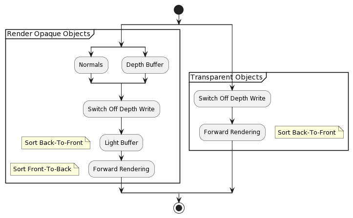
Compared to a deferred renderer, the light pre-pass renderer offers more flexibility regarding material implementations. Compared to a Z pre-pass renderer, it offers less flexibility but a flexible and fast multi-light solution.EngelShaderX709
Because the light buffer only has to hold light properties, the cost of rendering one light source is lower than for a similar setup in a deferred renderer.EngelShaderX709
- Advantages:
- Easier to retrofit into “traditional” rendering pipelinesLee09
- Lower memory and bandwidth usageLee09
- Can reuse your primary shaders for forward rendering of alphaLee09
- One material fetch per pixel regardless of number of lightsThibieroz11
- Disadvantages:
- Alpha blending is problematicLee09
- MSAA and alpha to coverage can help
- Encoding different material types is not elegantLee09
- Coherent fragment program dynamic branching can help
- 2x geometry pass too expensive on both CPU & GPUAndersson11
- Tile-based deferred shading has major potentialAndersson11
- Two geometry passes requiredThibieroz11
- Unique lighting modelThibieroz11
- Alpha blending is problematicLee09
Version AEngelSiggraph09
- Geometry Pass
- Fill up normal and depth buffer
- Lighting Pass
- Store light properties in light buffer
-
- Geometry Pass
- Fetch light buffer and apply different material terms per surface by reconstructing the lighting equation
- Geometry Pass
Version BEngelSiggraph09
Similar to S.T.A.L.K.E.R: Clear Skies
- Geometry Pass
- Fill up normal + spec. power and depth buffer and a color buffer for the ambient pass
- Lighting Pass
- Store light properties in light buffer
- Ambient + Resolve (MSAA) Pass
- Fetch light buffer use its content as diffuse and specular content and add the ambient term while resolving into the main buffer
Dragon Age IIPapathanasis11
- Extra pass to render scene normals
- Render all dynamic light spheres to a light buffer
- Allows for hundres of lights
Clustered Shading
Clustered shading explore higher dimensional tiles, which we collectively call clusters. Each cluster has a fixed maximum 3D extent.OlssonBilleterAssarssonHpg12
Deferred Algorithm:OlssonBilleterAssarssonHpg12
- Render scene to G-Buffers
- Cluster assignment
- Find unique clusters
- Assign lights to clusters
- Shade samples
Advantages:
- FlexibilityPersson15
- Forward rendering compatible
- Custom materials or light models
- Transparency
- Forward rendering compatible
- Deferred rendering compatiblePersson15
- Screen-space decals
- Performance
- SimplicityPersson15
- Unified lighting solution
- Easier to implement than full blown Tiled Deferred / Tiled Forward
- PerformancePersson15
- Typically same or better than Tiled Deferred
- Better worst-case performance
- Depth discontinuities? “It just works”
Avanlanche solution:Persson15
- Only spatial clustering
- 64 × 64 pixels, 16 depth slices
- CPU light assignment
- Compact memory structure easy
- Implicit cluster bounds only
- Scene-independent
- Deferred pass could potentially use explicit
- Exponential depth slicing
- Huge depth range! [0.1m ~ 50,000m]
- Default list
- [0.1, 0.23, 0.52, 1.2, 2.7, 6.0, 14, 31, 71, 161, 365, 828, 1880, 4270, 9696, 22018, 50000]
- Limit far to 500
- We have “distant lights” systems for light visualization beyond that
- [0.1, 0.17, 0.29, 0.49, 0.84, 1.43, 2.44, 4.15, 7.07, 12.0, 20.5, 35, 59, 101, 172, 293, 500]
- Special near 0.1 - 5.0 cluster
- Tweaked visually from player standing on flat ground
- [0.1, 5.0, 6.8, 9.2, 12.6, 17.1, 23.2, 31.5, 42.9, 58.3, 79.2, 108, 146, 199, 271, 368, 500]
Data Structure
- Cluster “pointers” in 3D texturePersson15
- R32G32_UINT
- R = Offset
- G = [PointLightCount, SpotLightCount]
- R32G32_UINT
- Light index list in texture bufferPersson15
- R16_UINT
- Tightly packed
- Light & shadow data in CBPersson15
- PointLight: 3 × float4
- SpotLight: 4 × float4
int3 tex_coord = int3(In.Position.xy, 0); // Screen-space position ...
float depth = Depth.Load(tex_coord);      // ... and depth

int slice = int(max(log2(depth * ZParam.x + ZParam.y) * scale + bias, 0));  // Look up cluster
int4 cluster_coord = int4(tex_coord >> 6, slice, 0);  // TILE_SIZE = 64

uint2 light_data = LightLookup.Load(cluster_coord); // Fetch light list
uint light_index = light_data.x;                    // Extract parameters
const uint point_light_count = light_data.y & 0xFFFF;
const uint spot_light_count  = light_data.y >> 16;

for (uint pl = 0; pl < point_light_counter; ++pl) // Point lights
{
  uint index = LightIndices[light_index++].x;

  float3 LightPos = PointLights[index].xyz;
  float3 Color = PointLights[index + 1].rgb;
  // Compute pointlight here ...
}

for (uint sl = 0; sl < spot_light_count; ++sl)    // Spot lights
{
  uint index = LightIndices[light_index++].x;

  float3 LightPos = SpotLights[index].xyz;
  float3 Color = SpotLights[index + 1].rgb;
  // Compute spotlight here ...
}
- Memory optimizationPersson15
- Naive approach: Allocate theoretical max
- All clusters address all lights
- Not likely
- Might be several megabytes
- Most never used
- All clusters address all lights
- Semi-conservative approach
- Construct massive worst-case scenario
- Multiply by 2, or what makes you comfortable
- Still likely only a small fraction of theoretical max
- Construct massive worst-case scenario
- Assert at runtime that you never go over allocation
- Warn if you ever get close
- Naive approach: Allocate theoretical max
Cluster Assignment
- Goal: compute an integer cluster key for a given view sample from the information available in the G-BufferOlssonBilleterAssarssonHpg12
- Use position, normal (optional)
- Regular subdivision / quantization of the sample positionsOlssonBilleterAssarssonHpg12
- Fast, predictable cluster sizes
- Uniform screen space tiling used in tiled deferred shading + extend this by also subdividing along the z-axis in view space (or NDC)OlssonBilleterAssarssonHpg12
- Due to non-linear nature of NDC, subdivide the z-axis in view space by spacing the divisions exponentiallyOlssonBilleterAssarssonHpg12
- Subdivision:OlssonBilleterAssarssonHpg12
- neark: near plane for a division k
- hk: depth of a division k
- neark = neark - 1 + hk - 1
- near0 = near
- h0 = 2 near tan θ / Sy
- 2θ: field of view
- Sy: number of subdivisions in the Y direction
- neark = near ( 1 + 2 tan θ / Sy)k

- Cluster key tuple (i, j, k):OlssonBilleterAssarssonHpg12

Granite:
- Instead of frustums, more grid-like structure provided much simpler culling mathArntzen20
Shadow of the Tomb Raider:Moradin19
- Light shapes are approximated with an icosahedron
- All frustums used for cone lights are just boxes scaled differently on both ends
Avalanche Studios:Persson15
- Want to minimize false positives
- Must be conservative
- But still tight
- Preferably exact
- But not too expensive
- Surprisingly hard!
- 99% frustum culling code useless
- Made for view-frustum culling
- Large frustum vs. small sphere
- We need small frustum vs. large sphere
- Sphere vs. six planes won’t do
- Made for view-frustum culling
- Pointlight Culling:
- Iterative sphere refinement
- Loop over z, reduce sphere
- Loop over y, reduce sphere
- Loop over x, test against sphere
- Culls better than AABB
- Similar cost
- Typically culling 20-30%
- Iterative sphere refinement
for (int z = z0; z <= z1; ++z)
{
  float4 z_light = light;
  if (z != center_z)
  {
    const ZPlane& plane = (z < center_z) ? z_planes[z + 1] : -z_planes[z];
    z_light = project_to_plane(z_light, plane);
  }

  for (int y = y0; y < y1; ++y)
  {
    float3 y_light = z_light;

    if (y != center_y)
    {
      const YPlane& plane = (y < center_y) ? y_planes[y + 1] : -y_planes[y];
      y_light = project_to_plane(y_light, plane);
    }

    int x = x0;
    do
    {
      ++x;
    } while (x < x1 && GetDistance(x_planes[x], y_light_pos) >= y_light_radius);

    int xs = x1;
    do
    {
      --xs;
    } while (xs >= x && -GetDistance(x_planes[xs], y_light_pos) >=- y_light_radius);

    for (--x; x <= xs; ++x)
    {
      light_lists.AddPointLight(base_cluster + x, light_index);
    }
  }
}
- Spotlight Culling:
- Iterative plane narrowing
- Find sphere cluster bounds
- In each six directions, do plane-cone test and shrink
- Cone vs. bounding-sphere cull remaining “cube”
- Iterative plane narrowing
Sparse vs Dense Cluster GridOlsson15
- Sparse Cluster Grid
- Only store cells that contain samples
- Requires pre-z pass / deferred
- No redundant light assignment
- Geometry info useful for other things
- Dense Cluster Grid
- Must assign lights to all clusters
- Can be done on CPU / Asynchronously
- Can access any point in view volume
- SAME shading cost as for sparse
Explicit vs Implicit ClusterOlsson15
- Explicit cluster bounds
- Actual bounding box of samples
- Some storage
- Some cost to build
- Tight bounds
- Extra geometry pass for forward shading
- Implicit cluster bounds
- Implied by grid coordinate
- No storage
- Can have large empty space
Finding Unique Clusters
- Local SortingOlssonBilleterAssarssonHpg12
- Sort samples in each screen space tile locally
- Allows us to:
- Perform the sorting operation in on-chip shared memory
- Use local indices to link back to the source pixel
- Allows us to:
- Extract unique clusters from each tile using a parallel compaction
- Compute and store a link from each sample to its associated cluster
- Globally unique list of clusters
- Sort samples in each screen space tile locally
- Cluster key defines implicit 3D bounds, and optionally an implicit normal coneOlssonBilleterAssarssonHpg12
- Compute the explicit bounds by performing a reduction over the samples in each clusterOlssonBilleterAssarssonHpg12
- e.g., Perform a min/max reduction to find the AABB enclosing each cluster
- Results of the reduction are stored separately in memoryOlssonBilleterAssarssonHpg12
Light AssignmentOlssonBilleterAssarssonHpg12
- Goal: calculate the list of lights influencing each cluster
- Fully hierarchical approach based on a spatial tree over the lights is better than tiled shading’s brute force approach
- Bounding Volume Hierarchy (BVH)
- Sort the lights according to the Z-order (Morton Code) based on the discretized centre position of each light
- Leaves of the search tree is get directly from the sorted data
- 32 consecutive leaves are grouped into a bounding volume (AABB) to form the first level above the leaves
- Next level is constructed by again combining 32 consecutive elements
- Continue until a single root element remains
- To construct upper levels of the tree, we launch a CUDA warp (32 threads) for each node to be constructed
- For each cluster, we traverse this BVH using depth-first traversal (warp is allocated)
- At each level, the bounding box of the cluster is tested against the bounding volumes of the child nodes
- For the leaf nodes, the sphere bounding the light source is used
- The branching factor of 32 allows efficient SIMD-traversal on the GPU and keeps the search tree relatively shallow (up to 5 levels)
- Avoid expensive recursion
- Support up to 32 million lights
ShadingOlssonBilleterAssarssonHpg12
To match the pixel and the clusters, we need a direct mapping between the cluster key and the index into the list of unique clusters.
In the sorting approach, we explicitly store this index for each pixel. When the unique cluster is established, store the index to the correct pixel in a full screen buffer.
Cluster Key PackingOlssonBilleterAssarssonHpg12
Allocate 8 bits to each i and j components, which allows up to 8192 × 8192 size RTs. Depth index k is determined from settings for the near and far planes and .
The paper uses 10 bits, 4 bits for the actually depth data, and 6 bits for the optional normal clustering.
Tile SortingOlssonBilleterAssarssonHpg12
To the cluster ke we attach an additional 10 bits of meta-data, which identifies the sample’s original position relative to its tile. We perfrom a tile-local sort of the cluster keys and the associated meta-data. The sort only considers the up-to 16 bits of the cluster key; the meta-data is used as a link back to the original sample after sorting. In each tile, we count the number of unique cluster keys. Using a prefix operation over the counts from each tile, we find the total number of unique cluster keys and assign each cluster a unique ID in the range [0…numClusters). We write the unique ID back to each pixel that is a member of the cluster. The unique ID also serves as an offset in memory to where the cluster’s data is stored.
Shadows
- Needs all shadow buffers upfrontPersson15
- One large atlas
- Variable size buffers
- Dynamically adjustable resolution
- One large atlas
- Lights are cheap, shadow maps are notPersson15
- Still need to be conservative about shadow casters
- Decouple light and shadow buffersPersson15
- Similar lights can share shadow buffers
- Userful for car lights etc.
Conservative Rasterization
- If any part of a primitive overlaps a pixel, that pixel is considered covered and is then rasterizedOrtegrenPersson16
Algorithm:OrtegrenPersson16
- For each light type:
- Shell pass
- Find min / max depths in every tile for every light
- Conservative RasterizationPersson15
- Fill pass
- Use the min / max depths and fill indices into the light linked list
- Compute shaderPersson15 * When all light types have been processed, light assignment is complete, and the light linked list can be used when shading geometry
- Shell pass
- Lights as meshesPersson15
- Typically very low-res
- Can be LODed
Light Shape Representation:
- Meshes are created as unit shapes, where vertices are constrained to -1 to 1 in the x-, y-, and z-directions
- To allow arbitrary scaling of the shape depending on the actual light size
Shell Pass
- Responsible for finding the clusters for a light shape that encompasses it in cluster space
- Finds the near / far clusters for each tile for each light and stores them in an R8G8 RT
- Number of RTs == Maximum number of visible lights for each light type
- All RTs have the same size and format and are set up in a
Texture2DArrayfor each light type - Sizes of the RTs are the same as the x- and y-dimensions of the cluster structure (tile dimension)
- Set
D3D12_CONSERVATIVE_RASTERIZATION_MODE_ONflag when creating a PSO. - Vertex Shader
- Each light type has its own custom vertex shader for translating, rotating, and scaling the light mesh to fit the actual light
SV_InstanceIDis used to extract the position, scale, and other properties to transform each vertex to the correct location in world space- Sent to GS containing the view-space position and its light ID
- Unit meshPersson15
- One draw-call per light typePersson15
- Geometry Shader
- Assigns array IDPersson15
- Can be done in VS now though
- Assigns array IDPersson15
- Pixel Shader
- Compute exact depth rangePersson15
- Texture Array, e.g. 24 × 16 × N, R8G8 formatPersson15
- Conservative RasterizationPersson15
- Touch all relevant tiles
- Compute exact depth range within pixelPersson15
- Triangle fully covers pixel
- Compute min & max from depth gradient
- Pixel fully covers triangle
- Use min & max from vertices
- Partial coverage
- Compute min & max at intersections
- Triangle fully covers pixel
- MIN blending resolves overlap
- Output 1-G to G to accomplish MINMAX
Fill Pass
- Compute shaderPersson15
- 1 thread per tile per light
- Light linked-list
Source Code Analysis
Root Signature:
- Default
- 1 CBV
- Camera information
- 1 SRV
- Point / spot lights
- 1 CBV
Draw:
- PSO Point
- Input Layout:
POSITION,R8G8B8A8_SNORM - Root Signature: Default
- VS:
LAPointLight.vertex - GS:
LA.geometry - PS:
LAfront.pixel
- Input Layout:
Future Work
- Clustering strategiesPersson15
- Screen-space tiles, depth vs. distance
- View-space cascades
- World space
- Allows light evaluation outside of view-frustum (reflections etc.)
- Dynamic adjustments?
- Shadows
- Culling clusters based on max-z in shadow buffer?
- Light assignment
- Asynchronous compute
Alternative Implementations
- Alternative clustering scheme
- World-space, fixed grid clustering schemePersson15
- Alternative light listPersson15
- Bitfield of lights
- Single fetch
- Constant and low memory requirements
- Suitable with low to moderate light counts
- Bitfield of lights
- Clustered lightmapping?Persson15
- LightMap stores light bitfield per texel
- Shadow fetched for enabled lights
- Dead space optimization?
- Limited dynamic lighting supportPersson15
- Turn lights on/off
- Vary light color, intensity, falloff
- Reduce radius
Per-Pixel Linked ListBezrati14
struct LightFragmentLink
{
  float m_LightDepthMax;
  float m_LightDepthMin;

  uint m_LightIndex;
  uint m_Next;
};
- Compressed version:
struct LightFragmentLink
{
  uint m_DepthInfo;
  uint m_IndexNetx;
}
- G-Buffer
- Fill Linked List
- Light G-Buffer
- Custom Materials
- Alpha
Light Linked List (LLL)
- Generate down-sized depth buffer
- Use conservative depth selection
- Use GatherRed
- Shader steps
- Software depth test
- Software test front faces
- Acquire min / max depth
- Allocate a LLL fragment
- Software depth test
Depth Test:
// If Z test fails for the front face, skip all fragments
if ((pFace == true) & (light_depth > depth_buffer))
{
  return;
}
- Depth Bounds
RWByteAddressBuffer - Encode Depth + ID
- 16 bits ID
- 16 bits Depth
uint new_bounds_info = (light_index << 16) | f32tof16(light_depth);
- Use
InterlockedExchange - Fragment Links
- Use a
RWStructuredBufferfor storage
- Use a
struct LightFragmentLink
{
  uint m_DepthInfo; // High bits min depth, low bits max depth
  uint m_IndexNext; // Light index and link to the next fragment
};
RWStructuredBuffer<LightFragmentLink> g_LightFragmentLinkedBuffer;
- Allocate LLL Fragment
- Increment current count
// Allocate
uint new_lll_idx = g_LightFragmentLinkedBuffer.IncrementCounter();

// Don't overflow
if (new_lll_idx >= g_VP_LLLMaxCount)
{
  return;
}
- Track last entry
- StartOffset
RWByteAddressBufferInterlockedExchange
- StartOffset
- Light fragment encoding
- Fill the linked light fragment and store it
// Final output
LightFragmentLink element;

// Pack the light depth
element.m_DepthInfo = (light_depth_min << 16)  light_depth_max;

// Index / Link
element.m_IndexNext = (light_index << 24) | (prev_lll_idx & 0xFFFFFFFF);

// Store the element
g_LightFragmentLinkedBuffer[new_lll_idx] = element;
Lighting the G-Buffer
- Draw full-screen quad
- Access the LLL
- Apply the light
Accessing the SRVs:
- Fetch the first linked element offset
- The first linked element is encoded in the lower 24 bits
uint src_index = LLLIndexFromScreenUVs(screen_uvs);
uint first_offset = g_LightStartOffsetView[src_index];

// Decode the first element index
uint element_index = (first_offset & 0xFFFFFF);
Light Loop:
- Start the lighting loop
- An element index equal
to 0xFFFFFFis invalid
- An element index equal
// Iterate over the light linked list
while (element_index != 0xFFFFFF)
{
  // Fetch
  LightFragmentLink element = g_LightFragmentLinkedView[element_index];

  // Update the next element index
  element_index = (element.m_IndexNext & 0xFFFFFF);
}
Decoding light depth:
- Decode the light min / max depth
- Compare the light depth
// Decode the light bounds
float light_depth_max = f16tof32(element.m_DepthInfo >> 0);
float light_depth_min = f16tof32(element.m_DepthInfo >> 16);

// Do depth bounds check
if ((l_depth > light_depth_max) || (l_depth < light_depth_min))
{
  continue;
}
Access light info:
- Fetch the full light information
// Decode the light index
uint light_index = (element.m_IndexNext >> 24);

// Access
GPULightEnv light_env = g_LinkedLightsEnvs[light_index];

// Detect the light type
switch (light_env.m_LightType)
{
  ...
3D Light GridAnagnostou17
- View space light grid of dimensions 29 x 16 x 32
- Screen space tile of 64 x 64 pixels and 32 z-partitions
- Partitioning is exponential
- Assign 9 lights and 2 reflection probes
- Axis-aligned box of each cell to perform light bounding volume intersections
- To store the light indices, a linked list is used which is then converted to a contiguous array during the “compact” pass
Optimizations
The most important optimization for the lighting pass is to render only those lights that actually affect the final image, and for those lights, render only the affected pixels.Shishkovtsov05Thibieroz11
- Social Stage:
- Filter the lights and effects on the scene to produce a smaller list of sources to be processed
- Execute visiblity and occlusion algorithms to discard lights whose influence is not appreciable
Project visible sources bounding objects into screen spaceCombine similar sources that are too close in screen space or influence almost the same screen area- Discard sources with a tiny contribution because of their projected bounding object being too small or too far
Check that more than a predefined number of sources do not affect each screen region. Choose the biggest, strongest, and closer sources.
- Filter the lights and effects on the scene to produce a smaller list of sources to be processed
- Individual Stage:
- Select the appropriate level of detail.
- Enable and configure the source shaders
Compute the minimum and maximum screen cord values of the projected bounding objectEnable the scissor testEnable the clipping planesRender a screen quad or the bounding object
- Constant Waterfall sucks!WhiteBarreBrisebois11
- Kills performance
- Use the aL register when iterating over lights
- If set properly, ALU / lighting will run at 100% efficiency
int lightCounter[4] = { count, start, step, 0 };
pDevice->SetPixelShaderConstantI(0, lightCounter, 1);
// NO

int tileLightCount : register(i0);
float4 lightParams[NUM_LIGHT_PARAMS] : register(c0);

[loop]
for (int iLight = 0;  // start
     iLight < tileLightCount; // count * step
     ++iLight)  // step
{
  float4 params1 = lightParams[iLight + 0]; // mov r0 c0[0 + aL]
  float4 params2 = lightParams[iLight + 1]; // mov r1 c0[1 + aL]
  float4 params3 = lightParams[iLight + 2]; // mov r2 c0[2 + aL]
}
- These shaders are ALU boundWhiteBarreBrisebois11
- Simplify math especially in the loops
- Get rid of complicated non 1:1 instructions (e.g. smoothstep)
- Play with microcode: -normalize(v) is faster than normalize(-v)
- Move code around to help with dual-issuing
- Use shader predicates to help the compiler
[flatten],[branch],[isolate],[ifAny],[ifAll], etc.- Tweak GPRs
- Use GPU freebiesWhiteBarreBrisebois11
- Texture sampler scale / bias (* 2 - 1)
- Simply / remove unnedded code via permutations
- Upload constants via the constnat buffer pointers
Sun Rendering
S.T.A.L.K.E.R case:Shishkovtsov05
- Skybox doesn’t need to be shaded
- Pixels facing away from the sun don’t need to have complex shading applied
- Pixels with AO term of 0 can also be excluded from processing
Killzone 2 case:Valient07
- Stencil mark potentially lit pixels
- Use only sun occlusion from G-Buffer
Level of Detail Lighting
Blending Cost
- Use
Discard()to get rid of pixels not contributing any light- Use this regardless of the light processing method used
- Can result in a significant increase in performance
Shadows
Shadow Maps
The key is using the little used variant known as forward shadow mapping. With forward shadow mapping the objects position is projected into shadow map space and then depths compared there.Calver03Thibieroz04
The first step is to calculate the shadow map; this is exactly the same as a conventional renderer.Calver03
When the light that generated the shadow map is rendered, the shadow map is attached to the light shader in the standard fashion (a cube map for the point light case).Calver03
- Point Light Shadow Maps
- Cube mapsKoonce07
- Else
- 2D texturesKoonce07
-
All textures are floating-point textures, multisample jitter sampling to smooth out the shadows.Koonce07
- Static shadow lights are built only once and reused each frameKoonce07
- Dynamic shadow maps are rebuilt each frameKoonce07
- By flagging geometry as static or dynamic, static shadow maps can cull out dynamic geometriesKoonce07
Efficient Omni Lights
Three major options:Shishkovtsov05
- Using a cube map for storing distance from the light center, R32F or R8G8B8A8 packed
- Using a 2D surface with “unrolled” cube-map faces, with reindexing done through a small cube map (called virtual shadow depth cube texture)
- Treating the point light as six spotlights and rendering each separately
| |Cube Map|Virtual Shadow Depth Cube Texture|Six Spotlights|
|—|——|———————————|————–|
|Scalability and Continuity|Low
Few Fixed sizes
All faces are the same|Moderate
Faces can be of different sizes, but only from a few fixed sets|Excellent
Any variation of sizes is possible|
|Hardware Filtering Support|No|Yes|Yes|
|Cost of Filtering|Moderate|Excellent for bilinear
Moderate for arbitrary percentage-closer filtering|Excellent|
|Render Target Switches|Six|One|One|
|Packing Support|No|Yes|Yes|
|Cost of Screen Space Stencil Masking|Low|Low|Moderate
Some stencil overdraw|
|Memory Cost and Bandwidth Usage|High
Surface is almost unusuable for everything else|Moderate
Few fixed sizes limits packing ability|Excellent|
Shishkovtsov05
Post Processing Phase
- Glow
- Auto-Exposure
- Distortion
- Edge-smoothing
- Fog
HDR
Render your scene to multiple 32 bit buffers, then use a 64 bit accumulation buffer during the light phase.Hargreaves04
Minor Architectures
The X-Ray Rendering ArchitectureLobanchikovGruen09
- G-Stage
- Light Stage
- Light Combine
- Transparent Objects
- Bloom/Exposition
- Final Combine-2
- Post-Effects
G-Stage
- Output geometry attributes (albedo, specular, position, normal, AO, material)
- MSAA output (subsample geometry data)
Light Stage
- Calculate lighting (diffuse light-RGB, specular light - intensity only)
- Interleaved rendering with shadowmap
- Draw emissive objects
- MSAA output (subsample lighting)
- Read from MSAA source (use G-Stage data)
Light Combine
- Deferred lighting is applied here
- Hemisphere lighting is calculated here (both using OA light-map and SSAO)
- Perform tone-mapping here
- Output Hi and Lo part of tone-mapped image into 2 RTs
- MSAA output (subsample data combination)
- Read from MSAA source (use G-Stage data and Light Stage data)
Transparent Objects
- Basic forward rendering
- MSAA output
Bloom / exposition
- Use Hi RT as a source for bloom / luminance estimation
Final combine-2
- Apply DoF, distortion, bloom
Post-Effects
- Apply black-outs, film grain, etc.
Light Indexed Deferred Rendering
Three basic render passes:Trebilco09
- Render depth only pre-pass
- Disable depth writes (depth testing only) and render light volumes into a light index texture
- Standard deferred lighting / shadow volume techniques can be used to find what fragments are hit by each light volume
- Render geometry using standard forward rendering
- Lighting is done using the light index texture to access lighting properties in each shader
In order to support multiple light indexes per-fragment, it would be ideal to store the first light index in the texture’s red channel, second light index in the blue index, etc.Trebilco09
- Advantages:Trebilco09
- vs Standard Deferred Rendering
- Uses forward rendering so no need for “fat buffers” to store normal/position type data
- Can layer on existing light schemes
- Small buffers size (varies depending on how many lights per fragment are supported)
- Light calculations like the reflection vector only needs to be calculated once
- MSAA can be supported with fewer resources
- Transparency can be supported
- vs Multi-pass Forward Rendering
- Can render lots of lights with only a fragment size cost per light
- Only two passes of the scene geometry - depth only pass then a forward render color pass
- Do not have to break geometry up into pieces for individual lighting - can render huge vertex buffers
- No Object → Light interactions need to be calculated on the CPU (for non-shadowing lights)
- Light calculations like reflection vectors only needs to be calculated once and texture lookups and filtering only need to be done once
- Can render “mesh-shaped” lights - not limited to sphere / cone shaped lights
- vs Multi-light Forward Rendering
- Can render lots of lights with only a fragment size cost per light
- Do not have to break geometry up into pieces for individual lighting - can render huge vertex buffers
- Can render “mesh-shaped” lights - not limited to sphere / cone shaped lights
- No Object → Light interactions need to be calculated on the CPU (for non-shadowing lights)
- vs Standard Deferred Rendering
- Disadvantages:Trebilco09
- vs Standard Deferred Rendering
- Exotic lighting types are harder to support (e.g., projected texture light)
- Need to set a limit on how many lights can hit each fragment (current implementation has a max of 16)
- Need to pass the vertex geometry twice - once for depth pre-pass and once for the forward pass
- Depth pre-pass is not vital for light indexed deferred rendering(LIDR) but it allows a lot of optimization
- Shadows are harder to support
- vs Multi-pass Forward Rendering
- Exotic lighting types are harder to support (e.g., projected texture light)
- Need to set a limit on how many lights can hit each fragment (current implementation has a max of 16)
- Requires a full screen buffer to store light index data
- All scene shaders need to be updated to support LIDR
- Slower on scenes that have few objects and lights
- Shadows are harder to support
- vs Multi-light Forward Rendering
- Exotic lighting types are harder to support (e.g., projected texture light)
- Need to set a limit on how many lights can hit each fragment (current implementation has a max of 16)
- Requires a full screen buffer to store light index data
- Can require two passes of scene geometry - depth only pass then a forward render color pass
- Slower on scenes that have few objects and lights
- Shadows are harder to support
- vs Standard Deferred Rendering
Matt Pettineo’s approachPettineo12
- Depth-only Prepass
- Depth buffer used by a compute shader to compute the list of intersecting lights per-tile
- List is stored in either an
R8_UINTorR16_UINTtyped buffer (8-bit for < 255 lights)
- List is stored in either an
Space MarineKimBarrero11
| Pass | Budget (ms) |
|---|---|
| Depth-Pre | 0.50 |
| G-Buffer + Linear Depth | 5.05 |
| AO | 2.25 |
| Lighting | 8.00 |
| Combiner Pass | 5.00 |
| Blend | 0.15 |
| Gamma Conversion | 1.30 |
| FX | 2.75 |
| Post Processing | 3.70 |
| UI | 0.50 |
| Total | 29.20 |
Screen-Space ClassificationKnightRitchieParrish11
Divided the screen into 4 × 4 pixel tiles. Each tile is classified according to the minimum global light properties it requires:
- Sky
- Fastest pixels because no lighting calculations required
- Sky color is simply copied directly from the G-Buffer
- Sun light
- Pixels facing the sun requires sun and specular lighting calculations (unless they’re fully in shadow)
- Solid shadow
- Pixels fully in shadow don’t require any shadow or sun light calculations
- Soft shadow
- Pixels at the edge of shadows require expensive eight-tap percentage closer filtering (PCF) unless they face away from the sun
- Shadow fade
- Pixels near the end of the dynamic shadow draw distance fade from full shadow to no shadow to avoid pops as geometry moves out of the shadow range
- Light scattering
- All but the nearest pixels
- Antialiasing
- Pixels at the edges of polygons require lighting calculations for both 2X MSAA fragments
Classify four during our screen-space shadow mask generation, the other three in a per-pixel pass.
Inferred Lighting
- Developed by Volition, Inc.
- Low-res MRT Geometry Pass
- Normals, DSF ID, Depth
- Low-res Lighting Pass
- Normals, Depth used
- Full-res Material Pass
- DSF ID and Low-res Lighting Pass used
Features:
- Lots of fully dynamic lights
- Integrated alpha lighting (no forward rendering)
- Hardware MSAA support
- Lit rain (IL required)
- Better foliage support (applies only to IL)
- Screen-space decals (enhanced by IL)
- Radial AO (RAO) (optimized by IL)
Hybrid Deferred RenderingSousaWenzelRaine13
- Deferred lighting still processed as usual
- L-Buffers now using BW friendlier R11G11B10F formats
- Precision was sufficient, since material properties not applied yet
- Deferred shading composited via fullscreen pass
- For more complex shading such as Hair or Skin, process forward passes
- Allowed us to drop almost all opaque forward passes
- Less drawcalls, but G-Buffer passes now with higher cost
- Fast Double-Z prepass for some of the closest geometry helps slightly
- Overwall was nice win, on all platforms*
- Less drawcalls, but G-Buffer passes now with higher cost
Destiny Engine Deferred RenderingTatarchukTchouVenzon13
- G-Buffers (96 bits)
- Depth, normal, material ids
- Opaque geometries + Decals
- Highly-compressed
- L-Buffers
- Lighting accumulation
- Light Geometry
- Lights
- Lit Result
- Full-screen shading
- Advantages:
- Memory footprint fits in EDRAM (96 bpp)
- Single pass over geometry (especially important for decoratos / foliage)
- Unified lighting + materials (no matrix of lights vs. geometry types like in Halo)
- Allows cheap deferred decals
- Complex material appearance
- Separate lighting / shading / geometry shaders simplifies shaders
- Disadvantages:
Rainbow Six SiegeElMansouri16
Opaque Rendering
- First person rendering
- 400 best occluders to depth buffer
- Generate Hi-Z
- Opaque culling & rendering
Shadow Rendering
- All shadows are cache based
- Used cached Hi-Z for culling
- Sunlight shadow done in full resolution
- Separate pass to relieve lighting resolve VGPR pressure
- Uses Hi-Z representation of the cached shadow map to reduce the work per pixel
- Local lights are resolved in a quarter resolution
- Resolved results stored in a texture array
- Lower VGPR usage on light accumulation
- Bilateral upscale
Lighting
- Clustered structure on the frustum
- 32 x 32 pixels based tile
- Z exponential distribution
- Hierarchical culling of light volume to fill the structure
- Local cubemaps regarded as lights
- Shadows, cubemaps, and gobos reside in texture arrays
- Deferred uses pre-resolved shadow texture array
- Forward uses shadows depth buffer array
Checkerboard Rendering
- Rendering to a 1/4 size (1/2 width by 1/2 height) resolution with MSAA 2X:
- We end up with half the samples of the full resolution image
- D3D MSAA 2X standard pattern
- 2 Color and Z samples
- Sample modifier or SV_SampleIndex input to enforce rendering all sample
- Each sample falls on the exact pixel center of full screen render target
Issues
Transparency
The best (in speed terms) we can do currently is to fall-back to a non-deferred lighting system for transparent surfaces and blend them in post-processing.Calver03Hargreaves04
Depth peeling is the ultimate solution, but is prohibitively expensive at least for the time being.Hargreaves04
StarCraft II uses multipass forward approach:FilionMcNaughton08
- Proved to be more scalable
- No need for more than a single shadow map buffer for the local lighting
StarCraft II’s simple layered system:
- Opaque Pass
- Create depth map from opaque objects
- Render opaque objects
- Apply depth-dependent post-processing effects
- Transparency Pass
- Render transparent objects back to front
- Key transparencies are allowed to perform pre-pass where they overwrite the g-buffer
- Since all post-processing on previous g-buffer data has been applied, that information is no longer needed
- Update AO deferred buffer
- Render the transparency
- Perform DoF pass on the areas covered by the transparency
Memory
No solutions but a warning that deferred lighting has a number of large render-targets.Calver03
Anti-Aliasing
- Super sampling lighting is a costly optionHargreavesHarris04
- Filter object edgesHargreavesHarris04
Antialiasing becomes solely the responsibility of the application and the shader; we cannot rely on the GPU alone.Shishkovtsov05
Edge Detection
Edge-smoothing filter by Fabio05.Placeres06:
- Edge-detection scan is applied to the screen. The filter uses discontinuities in the positions and normal stored in the GBuffer. The results can be stored in the stencil buffer as a mask for the next step.
- The screen is blurred using only the pixels that are edges
- These pixels are masked in the stencil buffer
- However, color bleeding can occur (e.g., background color bleeding into the character)
- Thus, a kernel is applied to the edge pixels, but only the closest to the camera are combined
- Cloor bleeding reduction
Pixel Edge Detection (Pixel Shader):Thibieroz09
// Pixel shader to detect pixel edges
// Used with the following depth-stencil state values:
// DepthEnable = TRUE
// DepthFunc = Always
// DepthWriteMask = ZERO
// StencilEnable = TRUE
// Front/BackFaceStencilFail = Keep
// Front/BackfaceStencilDepthFail = Keep
// Front/BackfaceStencilPass = Replace;
// Front/BackfaceStencilFunc = Always;
// The stencil reference value is set to 0x80

float4 PSMarkStencilWithEdgePixels( PS_INPUT input ) : SV_TARGET
{
  // Fetch and compare samples from GBuffer to determine if pixel
  // is an edge pixel or not
  bool bIsEdge = DetectEdgePixel(input);

  // Discard pixel if non-edge (only mark stencil for edge pixels)
  if (!bIsEdge) discard;

  // Return color (will have no effect since no color buffer bound) return
  float4(1,1,1,1);
}
Centroid-Based Edge Detection
An optimized way to detect edges is to leverage the GPU’s fixed function resolve feature. Centroid sampling is used to adjust the sample position of an interpolated pixel shader input so that it is contained within the area defined by the multisamples covered by the triangle.Thibieroz09
Centroid sampling can be used to determine whether a sample belongs to an edge pixel or not.Thibieroz09
This MSAA edge detection technique is quite fast, especially compared to a custom method of comparing every G-Buffer normal and depth samples. It only requires a few bits of storage in a G-Buffer render target.Thibieroz09
- This is a neat trick, but is not that usefulThibieroz11
- Produces too many edges that don’t need to be shaded per sample
- Especially when tessellation is used!!
- Doesn’t detect edges from transparent textures
S.T.A.L.K.E.R.Shishkovtsov05
Our solution was to trade some signal frequency at the discontinuities for smoothness, and to leave other parts of the image intact. We detect discontinuities in both depth and normal direction by taking 8+1 samples of depth and finding how depth at the current pixel differs from the ideal line passed through opposite corner points. The normals were used to fix issues such as a wall perpendicular to the floor, where the depth forms a perfect line (or will be similar at all samples) but an aliased edge exists. The normals were processed in a similar cross-filter manner, and the dot product between normals was used to determine the presence of an edge.
struct v2p
{
  float4 tc0: TEXCOORD0; // Center
  float4 tc1: TEXCOORD1; // Left Top
  float4 tc2: TEXCOORD2; // Right Bottom
  float4 tc3: TEXCOORD3; // Right Top
  float4 tc4: TEXCOORD4; // Left Bottom
  float4 tc5: TEXCOORD5; // Left / Right
  float4 tc6: TEXCOORD6; // Top /Bottom
};

/////////////////////////////////////////////////////////////////////
uniform sampler2D s_distort;
uniform half4 e_barrier;  // x=norm(~.8f), y=depth(~.5f)
uniform half4 e_weights;  // x=norm, y=depth
uniform half4 e_kernel;   // x=norm, y=depth
/////////////////////////////////////////////////////////////////////

half4 main(v2p I) : COLOR
{
  // Normal discontinuity filter
  half3 nc = tex2D(s_normal, I.tc0);
  half4 nd;
  nd.x = dot(nc, (half3)tex2D(s_normal, I.tc1));
  nd.y = dot(nc, (half3)tex2D(s_normal, I.tc2));
  nd.z = dot(nc, (half3)tex2D(s_normal, I.tc3));
  nd.w = dot(nc, (half3)tex2D(s_normal, I.tc4));
  nd -= e_barrier.x;
  nd = step(0, nd);
  half ne = saturate(dot(nd, e_weights.x));

  // Opposite coords
  float4 tc5r = I.tc5.wzyx;
  float4 tc6r = I.tc6.wzyx;

  // Depth filter : compute gradiental difference:
  // (c-sample1)+(c-sample1_opposite)
  half4 dc = tex2D(s_position, I.tc0);
  half4 dd;
  dd.x = (half)tex2D(s_position, I.tc1).z +
    (half)tex2D(s_position, I.tc2).z;
  dd.y = (half)tex2D(s_position, I.tc3).z +
    (half)tex2D(s_position, I.tc4).z;
  dd.z = (half)tex2D(s_position, I.tc5).z +
    (half)tex2D(s_position, tc5r).z;
  dd.w = (half)tex2D(s_position, I.tc6).z +
    (half)tex2D(s_position, tc6r).z;
  dd = abs(2 * dc.z - dd)- e_barrier.y;
  dd = step(dd, 0);
  half de = saturate(dot(dd, e_weights.y));

  // Weight
  half w = (1 - de * ne) * e_kernel.x;
  // 0 - no aa, 1=full aa
  // Smoothed color
  // (a-c)*w + c = a*w + c(1-w)
  float2 offset = I.tc0 * (1-w);
  half4 s0 = tex2D(s_image, offset + I.tc1 * w);
  half4 s1 = tex2D(s_image, offset + I.tc2 * w);
  half4 s2 = tex2D(s_image, offset + I.tc3 * w);
  half4 s3 = tex2D(s_image, offset + I.tc4 * w);
  return (s0 + s1 + s2 + s3)/4.h;
}
Tabula RasaKoonce07
Modified S.T.A.L.K.E.R.’s algorithm to be resolution independent.
We looked at changes in depth gradients and changes in normal angles by sampling all eight neighbors surrounding a pixel. We compare the maximum change in depth to the minimum change in depth to determine how much of an edge is present. By comparing relative changes in this gradient instead of comparing the gradient to fixed values, we are able to make the logic resolution independent.
We compare the changes in the cosine of the angle between the center pixel and its neighboring pixels along the same edges at which we test depth gradients.
The output of the edge detection is a per-pixel weight between zero and one. The weight reflects how much of an edge the pixel is on. We use this weight to do four bilinear samples when computing the final pixel color. The four samples we take are at the pixel center for a weight of zero and at the four corners of the pixel for a weight of one. This results in a weighted average of the target pixel with all eight of its neighbors.
////////////////////////////    // Neighbor offset table    ////////////////////////////
const static float2 offsets[9] =
{
  float2( 0.0,  0.0), //Center       0
  float2(-1.0, -1.0), //Top Left     1
  float2( 0.0, -1.0), //Top          2
  float2( 1.0, -1.0), //Top Right    3
  float2( 1.0,  0.0), //Right        4
  float2( 1.0,  1.0), //Bottom Right 5
  float2( 0.0,  1.0), //Bottom       6
  float2(-1.0,  1.0), //Bottom Left  7
  float2(-1.0,  0.0)  //Left         8
};

float DL_GetEdgeWeight(in float2 screenPos)
{
  float Depth[9];
  float3 Normal[9];

  //Retrieve normal and depth data for all neighbors.
  for (int i=0; i<9; ++i)
  {
    float2 uv = screenPos + offsets[i] * PixelSize;
    Depth[i] = DL_GetDepth(uv);   //Retrieves depth from MRTs

    Normal[i]= DL_GetNormal(uv);  //Retrieves normal from MRTs
  }

  //Compute Deltas in Depth.
  float4 Deltas1;
  float4 Deltas2;
  Deltas1.x = Depth[1];
  Deltas1.y = Depth[2];
  Deltas1.z = Depth[3];
  Deltas1.w = Depth[4];
  Deltas2.x = Depth[5];
  Deltas2.y = Depth[6];
  Deltas2.z = Depth[7];
  Deltas2.w = Depth[8];

  //Compute absolute gradients from center.
  Deltas1 = abs(Deltas1 - Depth[0]);
  Deltas2 = abs(Depth[0] - Deltas2);

  //Find min and max gradient, ensuring min != 0
  float4 maxDeltas = max(Deltas1, Deltas2);
  float4 minDeltas = max(min(Deltas1, Deltas2), 0.00001);

  // Compare change in gradients, flagging ones that change
  // significantly.
  // How severe the change must be to get flagged is a function of the
  // minimum gradient. It is not resolution dependent. The constant
  // number here would change based on how the depth values are stored
  // and how sensitive the edge detection should be.
  float4 depthResults = step(minDeltas * 25.0, maxDeltas);

  //Compute change in the cosine of the angle between normals.
  Deltas1.x = dot(Normal[1], Normal[0]);
  Deltas1.y = dot(Normal[2], Normal[0]);
  Deltas1.z = dot(Normal[3], Normal[0]);
  Deltas1.w = dot(Normal[4], Normal[0]);
  Deltas2.x = dot(Normal[5], Normal[0]);
  Deltas2.y = dot(Normal[6], Normal[0]);
  Deltas2.z = dot(Normal[7], Normal[0]);
  Deltas2.w = dot(Normal[8], Normal[0]);
  Deltas1 = abs(Deltas1 - Deltas2);

  // Compare change in the cosine of the angles, flagging changes
  // above some constant threshold. The cosine of the angle is not a
  // linear function of the angle, so to have the flagging be
  // independent of the angles involved, an arccos function would be
  // required.
  float4 normalResults = step(0.4, Deltas1);
  normalResults = max(normalResults, depthResults);

  return (normalResults.x + normalResults.y +
    normalResults.z + normalResults.w) * 0.25;
}
MSAA
MSAA allows a scene to be rendered at a higher resolution without having to pay the cost of shading more pixels.Thibieroz09
- To support MSAA, the MRTs must be rendered with MSAA.
- Forward shading
- Each object is shaded and rendered directly into a multisampled surface
- Once all objects have been rendered, a resolve operation is required to convert the multi-sampled render target into a final, anti-aliased image
- Deferred shading
- G-Buffer’s multisampled RTs are simply intermediate storage buffers leading to the construction of the final image
- Once all shading contributions to the scene have been rendered onto the multisampled accumulation buffer, then the resolve operation can take place on this buffer to produce the final, anti-aliased image
- Multisampled resources:
- G-Buffer RTs
- Accumulation buffer receiving the contribution of shading passes and further rendering
- Depth-stencil buffer
- In order to produce accurate results for MSAA, it is essential that the pixel shaders used during the shading passes are executed at per-sample frequency
- However, this has a significant impact on performance
- A sensible optimization is to detect pixels whose samples have different values and only perform per-sample pixel shader execution on those “edge” pixels
Run light shader at pixel resolutionValient07
Read G-Buffer for both pixel samplesCompute lighting for both samplesAverage results and add to frame buffer
S.T.A.K.E.R: Clear Skies:LobanchikovGruen09
- Render to MSAA G-Buffer
- Mask edge pixels
- Process only subsample #0 for plain pixels
- Output to all subsamples
- Process each subsample for edge pixels independently
- Early stencil hardware minimizes PS overhead
For each shader
  Plain pixel: run shader at pixel frequency
  Edge pixel: run at subpixel frequency
MSAA Compute Shader Lighting
- Only edge pixels need full per-sample lightingAndersson11
- But edges have bad screen-space coherency! InefficientStewartThomas13
- Bad for branchingStewartThomas13
- But edges have bad screen-space coherency! InefficientStewartThomas13
- Compute Shader can build efficient coherent pixel listAndersson11
- Evaluate lighting for each pixel (sample 0)
- Determine if pixel requires per-sample lighting
- If so, add to atomic list in shared memory
- When all pixels are done, synchronize
- Go through and light sample 1-3 for pixels in list
Comparisons
| |Deferred |Tiled Deferred |Tiled Forward| |————————-|———-|————————–|————-| |Innermost loop |Pixels |Lights |Lights | |Light data access pattern|Sequential|Random |Random | |Pixel data access pattern|Random |Sequential |Sequential | |Re-use Shadow Maps |Yes |No |No | |Shading Pass |Deferred |Deferreda|Geometry | |G-Buffers |Yes |Yes |No | |Overdraw of shading |No |No |Yes | |Transparency |Difficult |Simple |Simple | |Supporting FSAA |Difficult |Difficult |Trivial | |Bandwidth Usage |High |Low |Low | |Light volume intersection|Per Pixel |Per Tile |Per Tile | OlssonAssarsson11
EA. SIGGRAPH. 2011.
| Light Type (8 lights/tile, every tile) |
Performance |
|---|---|
| Point | 4.0 ms |
| Point (with Spec) | 7.8 ms |
| Cone | 5.1 ms |
| Cone (with Spec) | 5.3 ms |
| Line | 5.8 ms |
- Classification: 1.35ms (with resolves)
Deferred vs Forward+
- DeferredPesce20
- Frostbite
- Guerrilla’s Decima
- Call of Duty BO3/4/CW
- Red Dead Redemption 2
- Naughty Dog’s Uncharted/TLOU
- Forward+Pesce20
- Doom
- Call of Duty: Modern Warfare / Warzone
References
2003
Photo-realistic Deferred Lighting. Dean Calver, Climax / Snapshot Games. Beyond3D.
2004
Deferred Shading. Shawn Hargreaves, Climax / Microsoft. GDC 2004
Deferred Shading. Shawn Hargreaves, Climax / Microsoft. Mark Harris, NVIDIA. NVIDIA Developers Conference 2004.
Deferred Shading with Multiple Render Targets. Nicolas Thibieroz, PowerVR Technologies / AMD. ShaderX2.
2005
Deferred Shading in S.T.A.L.K.E.R.. Oleksandr Shyshkovtsov, GSC Game World / 4A Games. GPU Gems 2.
2006
Overcoming Deferred Shading Drawbacks. Frank Puig Placeres, University of Informatic Sciences / Amazon. ShaderX5.
2007
Deferred Shading in Tabula Rasa. Rusty Koonce, NCSoft Corporation / Facebook. GPU Gems 3.
Deferred Rendering in Killzone 2. Michal Valient, Guerilla Games / Epic Games. Developer Conference 2007.
Optimizing Parallel Reduction in CUDA. Mark Harris, NVIDIA.
2008
The Technology of Uncharted: Drake’s Fortune. Christophe Balestra, Naughty Dog / Retired. Pål-Kristian Engstad, Naughty Dog / Apple. GDC 2008.
StarCraft II: Effects & Techniques. Dominic Filion, Blizzard Entertainment / Snap Inc.. Rob McNaughton, Blizzard Entertainment. SIGGRAPH 2008: Advances in Real-Time Rendering in 3D Graphics and Games Course.
2009
Parallel Graphics in Frostbite - Current Future. Johan Andersson, DICE / Embark Studios.
SIGGRAPH 2009: Beyond Programmable Shading Course.
Designing a Renderer for Multiple Lights: The Light Pre-Pass Renderer. Wolfgang Engel, Rockstar Games / The Forge. ShaderX7.
Light Pre-Pass; Deferred Lighting: Latest Development. Wolfgang Engel, Rockstar Games / The Forge. SIGGRAPH 2009: Advances in Real-Time Rendering in Games Course.
Pre-lighting in Resistance 2. Mark Lee, Insomniac Games / Walt Disney Animation Studios. GDC 2009.
GSC Game World’s S.T.A.L.K.E.R: Clear Sky—A Showcase for Direct3D 10.0/1. Igor A. Lobanchikov, GSC Game World / Retired. Holger Gruen, AMD. GDC 2009.
Deferred Lighting and Post Processing on PLAYSTATION 3. Matt Swoboda, Sony Computer Entertainment / Notch. GDC 2009.
Deferred Shading with Multisampling Anti-Aliasing in DirectX 10. Nicolas Thibieroz, AMD. GDC 2009. ShaderX7.
Light-Indexed Deferred Rendering. Damian Trebilco, THQ / Situ Systems. ShaderX7.
Compact Normal Storage for small G-Buffers. Aras Pranckevičius, Unity Technologies / Freelancer. Blog.
2010
CryENGINE 3: Reaching the Speed of Light. Anton Kaplanyan, Crytek / Intel Corporation. SIGGRAPH 2010: Advances in Real-Time Rendering in Games Course.
Deferred Rendering for Current and Future Rendering Pipelines. Andrew Lauritzen, Intel Corporation. SIGGRAPH 2010: Beyond Programmable Shader Course.
2011
DirectX 11 Rendering in Battlefield 3. Johan Andersson, DICE / Embark Studios. GDC 2011
Rendering Tech of Space Marine. Pope Kim, Relic Entertainment / POCU. Daniel Barrero, Relic Entertainment. KGC 2011.
Screen-Space Classification for Efficient Deferred Shading. Balor Knight, Black Rock Studio. Matthew Ritchie, Black Rock Studio. George Parrish, Black Rock Studio. Game Engine Gems 2.
Tiled Shading. Ola Olsson, Chalmers University of Technology / Epic Games. Ulf Assarsson, Chalmers University of Technology. Journal of Graphics, GPU, and Game Tools.
Dragon Age II DX11 Technology. Andreas Papathanasis, BioWare / Parallel Space Inc.. GDC 2011.
Deferred Shading Optimizations. Nicolas Thibieroz, AMD. GDC 2011.
More Performance! Five Rendering Ideas from Battlefield 3 and Need For Speed: The Run. John White, EA Black Box / Roblox. Colin Barré-Brisebois, DICE / SEED. SIGGRAPH 2011: Advances in Real-Time Rendering in Games Course.
2012
Forward+: Bringing Deferred Lighting to the Next Level. Takahiro Harada, AMD. Jay McKee, AMD. Jason C. Yang, AMD / DGene. Eurographics 2012.
A 2.5D Culling for Forward+. Takahiro Harada, AMD. SIGGRAPH ASIA 2012.
Lighting & Simplifying Saints Row: The Third. Scott Kircher, Volition. GDC 2012.
Clustered Deferred and Forward Shading. Ola Olsson, Chalmers University of Technology / Epic Games. Markus Billeter, Chalmers University of Technology. Ulf Assarsson, Chalmers University of Technology. HPG 2012.
Tiled and Clustered Forward Shading: Supporting Transparency and MSAA. Ola Olsson, Chalmers University of Technology / Epic Games. Markus Billeter, Chalmers University of Technology. Ulf Assarsson, Chalmers University of Technology. SIGGRAPH 2012: Talks.
Light Indexed Deferred Rendering. Matt Pettineo, Ready at Dawn. The Danger Zone Blog.
2013
Tiled Forward Shading. Ola Olsson, Chalmers University of Technology / Epic Games. Markus Billeter, Chalmers University of Technology / University of Leeds. Ulf Assarsson, Chalmers University of Technology. GPU Pro 4.
Forward+: A Step Toward Film-Style Shading in Real Time. Takahiro Harada, AMD. Jay McKee, AMD. Jason C. Yang, AMD / DGene. GPU Pro 4.
The Rendering Technologies of Crysis 3. Tiago Sousa, Crytek / id Software. Carsten Wenzel, Crytek / Cloud Imperium Games. Chris Raine, Crytek. GDC 2013.
CryENGINE 3: Graphics Gems. Tiago Sousa, Crytek / id Software. Nickolay Kasyan, Crytek / AMD. Nicolas Schulz, Crytek. SIGGRAPH 2013: Advances in Real-Time Rendering in 3D Graphics and Games Course.
Tiled Rendering Showdown: Forward++ vs. Deferred Rendering. Jason Stewart, AMD. Gareth Thomas, AMD. GDC 2013.
Destiny: From Mythic Science Fiction to Rendering in Real-Time. Natalya Tatarchuk, Bungie / Unity Technologies. Chris Tchou, Bungie. Joe Venzon, Bungie. SIGGRAPH 2013: Advances in Real-Time Rendering in 3D Graphics and Games Course.
2014
inFAMOUS Second Son Engine Postmortem. Adrian Bentley, Sucker Punch Productions. GDC 2014.
Real-Time Lighting via Light Linked List. Abdul Bezrati, Insomniac Games. SIGGRAPH 2014: Advances in Real-Time Rendering in 3D Graphics and Games Course.
Forward Clustered Shading. Marc Fauconneau Dufresne, Intel Corporation. Intel Software Developer Zone.
The Making of Forza Horizon 2. Richard Leadbetter, Digital Foundary. Eurogamer.net.
Crafting a Next-Gen Material Pipeline for The Order: 1886. David Neubelt, Ready at Dawn. Matt Pettineo, Ready at Dawn. GDC 2014.
Notes on Real-Time Renderers. Angelo Pesce, Activision / Roblox. C0DE517E Blog.
Moving to the Next Generation—The Rendering Technology of Ryse. Nicolas Schulz, Crytek. GDC 2014.
Compute Shader Optimizations for AMD GPUs: Parallel Reduction. Wolfgang Engel, Rockstar Games / The Forge. Diary of a Graphics Programmer.
Survey of Efficient Representations for Independent Unit Vectors. Zina H. Cigolle, Williams College / Stripe. Sam Donow, Williams College / Hudson River Trading. Daniel Evangelakos, Williams College / Olive. Michael Mara, Williams College / Luminary Cloud. Morgan McGuire, Williams College / Roblox. Quirin Meyer, Elektrobit / Hochschule Coburg. JCGT.
2015
Real-Time Lighting via Light Linked List. Abdul Bezrati, Insomniac Games. GPU Pro 6.
More Efficient Virtual Shadow Maps for Many Lights. Ola Olsson, Chalmers University of Technology / Epic Games. Markus Billeter, Chalmers University of Technology. Erik Sintorn, Chalmers University of Technology. IEEE Transactions on Visualization and Computer Graphics.
Practical Clustered Shading. Emil Persson, Avalanche Studios / Elemental Games. SIGGRAPH 2015: Real-Time Many-Light Management and Shadows with Clustered Shading Course.
Notes on G-Buffer normal encodings. Angelo Pesce, Activision / Roblox. C0DE517E Blog.
Introduction to Real-Time Shading with Many Lights. Ola Olsson, Chalmers University of Technology / Epic Games. SIGGRAPH 2015: Real-Time Many-Light Management and Shadows with Clustered Shading Course.
Rendering the Alternate History of The Order: 1886. Matt Pettineo, Ready at Dawn. SIGGRAPH 2015: Advances in Real-Time Rendering in Games Course.
Compute-Based Tiled Culling. Jason Stewart, AMD. GPU Pro 6.
Advancements in Tiled-Based Compute Rendering. Gareth Thomas, AMD. GDC 2015.
2016
Deferred Lighting in Uncharted 4. Ramy El Garawany, Naughty Dog / Google. SIGGRAPH 2016: Advances in Real-Time Rendering in Games Course.
Rendering Tom Clancy’s Rainbow Six Siege. Jalal El Mansouri, Ubisoft Montréal / Haven Studios Inc.. GDC 2016
Clustered Shading: Assigning Lights Using Conservative Rasterization in DirectX 12. Kevin Örtegren, Avalanche Studios / Epic Games. Emil Persson, Avalanche Studios / Elemental Games. GPU Pro 7.
Tiled Shading: Light Culling—Reaching the Speed of Light. Dmitry Zhdan, NVIDIA. GDC 2016.
2017
How Unreal Renders a Frame. Kostas Anagnostou, Radiant Worlds / Playground Games. Interplay of Light Blog.
Improved Culling for Tiled and Clustered Rendering. Michal Drobot, Infinity Ward. SIGGRAPH 2017: Advances in Real-Time Rendering in Games Course.
Cull That Cone! Improved Cone/Spotlight Visibility Tests for Tiled and Clustered Lighting. Bartłomiej Wroński, Santa Monica Studio / NVIDIA. Bart Wronski Blog.
2018
The Road Toward Unified Rendering with Unity’s High Definition Render Pipeline. Sébastien Lagarde, Unity Technologies. Evgenii Golubev, Unity Technologies. SIGGRAPH 2018: Advances in Real-Time Rendering in Games Course.
2019
Under the Hood of Shadow of the Tomb Raider. m0radin. m0rad.in Blog.
2020
Real-Time Samurai Cinema: Lighting, Atmosphere, and Tonemapping in Ghost of Tsushima. Jasmin Patry, Sucker Punch Productions. SIGGRAPH 2021: Advances in Real-Time Rendering in Games Course.
Clustered Shading Evolution in Granite. Hans-Kristian Arntzen, Arntzen Software AS. Maister’s Graphics Adventures Blog.
Graphics Study: Red Dead Redemption 2. Hüseyin, Our Machinery. imgeself Blog.
Hallucinations re: the rendering of Cyberpunk 2077. Angelo Pesce, Roblox. C0DE517E Blog.
2021
The Rendering of Jurassic World: Evolution. The Code Corsair. The Code Corsair Blog.
The Rendering of Mafia: Definitive Edition. The Code Corsair. The Code Corsair Blog.
Digital combat simulator: frame analysis. Thomas Poulet, Ubisoft Berlin / Huawei. Blog.
People by Company
- Z Pre-Pass
@startuml
start
split
group Render Opaque Objects
    :Depth Buffer;
floating note left: Z Pre-Pass
floating note right: Sort Front-To-Back
    :Switch Off Depth Write;
    :Forward Rendering;
floating note left: Sort Front-To-Back
end group
split again
group Transparent Objects
    :Switch Off Depth Write;
    :Forward Rendering;
    floating note right: Sort Back-To-Front
end group
end split
stop
@enduml